Figure 1: The four-stage failure chain of scale accumulation — from initial scaling to passage blockage, local boiling, and eventually coil burnout.
Problem Definition: The Real Root Cause of Coil Burnout
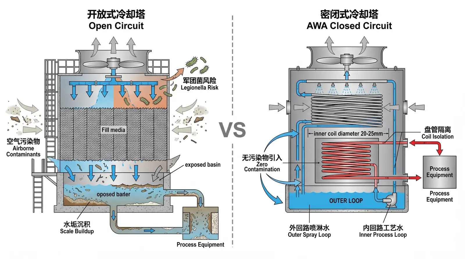
In casting, forging, and heat-treatment industries, induction coil burnout in medium-frequency induction heating furnaces is one of the most common causes of unplanned downtime. When a burned-out coil is removed and cut open for inspection, the internal cooling water passages are almost always fully blocked by hard scale.
This is not an isolated case. There is an irreconcilable physical conflict between an open cooling tower and the structure of an induction furnace coil: an open tower continuously concentrates minerals in the circulating water, while the copper tube inside the induction furnace coil has an inner diameter of only 8–15 mm, making it an ideal location for mineral deposition.
Physical Principle: The Four-Stage Failure Chain
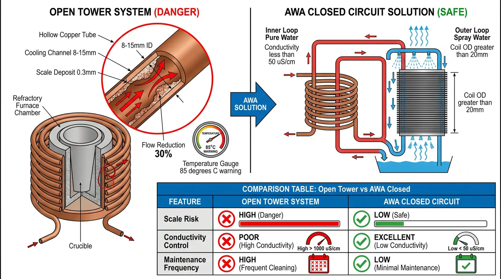
First 6 Months: How 0.3 mm of Scale Increases Thermal Resistance by 520 Times
When the concentration cycle of open-tower circulating water reaches 3–4, the Ca²⁺ concentration rises to 600–800 mg/L. After circulating water enters the coil copper tube, the tube wall temperature, usually 60–80°C, is much higher than the water temperature of 30–35°C, so CaCO₃ preferentially precipitates on the tube wall. In the early stage, scale thickness is about 0.1–0.3 mm. At this stage, the effect on flow is not obvious, but thermal resistance has already increased significantly.
Thermal resistance calculation: the thermal conductivity of the copper tube wall is λ_Cu = 390 W/(m·K), while the thermal conductivity of CaCO₃ scale is λ_scale ≈ 0.5–1.0 W/(m·K). The thermal resistance of a 0.3 mm scale layer is R_scale = δ/λ = 0.0003/0.75 ≈ 4×10⁻⁴ m²·K/W, while the thermal resistance of a copper tube wall of the same thickness is only 7.7×10⁻⁷ m²·K/W. The thermal resistance of the scale is about 520 times that of copper.
6 to 12 Months: Passage Reduction Lowers Flow from Turbulent to Transitional
As scale continues to accumulate and the inner diameter decreases from 15 mm to 12 mm, the cross-sectional area is reduced by 36%. Flow velocity decreases, and the Reynolds number drops from the turbulent region (Re > 10000) to the transitional region (Re < 4000). The convective heat transfer coefficient h decreases from 5000 W/(m²·K) to about 2000 W/(m²·K). Cooling capacity declines, and the coil temperature begins to rise.
12 to 18 Months: Local Boiling on the Tube Wall Accelerates Scale Deposition
When the tube wall temperature exceeds the saturation temperature at local pressure, about 100°C, local boiling, or nucleate boiling, appears near the tube wall. During bubble formation and detachment from the tube wall, dissolved minerals become highly concentrated around the bubbles, increasing the scale accumulation rate by 3–5 times. The passage narrows further and forms a positive feedback loop.
Final Stage: Temperature Runaway Causes Insulation Breakdown and Copper Tube Melt-Through
When the outer wall temperature of the coil copper tube exceeds the softening temperature of copper, above 200°C, the copper tube deforms. When it exceeds the temperature limit of the insulating varnish, usually 130–180°C for Class B insulation, turn-to-turn insulation breaks down and a short circuit occurs. Alternatively, if the inside of the copper tube becomes completely blocked and cooling water flow is cut off, the copper tube may melt through within minutes due to Joule heat.
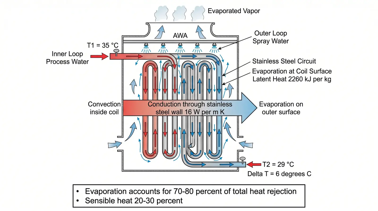
COOLTEK Solution: A Closed Circuit Physically Cuts Off the Failure Chain
The process water in the inner circuit of the AWA closed-circuit cooling tower is not exposed to the atmosphere, so there is no evaporative concentration process. Makeup water for the inner circuit uses softened water with hardness below 50 mg/L. After corrosion and scale inhibitors are added, circulating water conductivity is maintained below 250 μS/cm, and Ca²⁺ concentration remains below 50 mg/L. Under these water-quality conditions, the Langelier Saturation Index, or LSI, of CaCO₃ is below 0. The circulating water is in a slightly corrosive state and does not precipitate scale on the tube wall.
The first link in the failure chain, mineral concentration, is physically cut off, so the following three stages do not occur.
Before-and-after comparison: a foundry in Dong Nai Province, 500 kW medium-frequency furnace, retrofit data from 2023:
| Indicator | Before Retrofit (Open Tower) | After Retrofit (AWA Closed-Circuit Tower) |
|---|---|---|
| Coil replacement interval | Average 14 months per replacement | No replacement after 36 months following retrofit; still under monitoring |
| Circulating water conductivity | 1200–1800 μS/cm | 180–220 μS/cm |
| Coil outlet water temperature | 45–52°C; alarm value 45°C | 32–36°C |
| Annual maintenance cost | About VND 320 million, including coil replacement and downtime loss | About VND 40 million, routine water treatment |
Standards Verification: Cooling Water Quality Requirements of Mainstream Induction Furnace OEMs
Cooling water quality specifications from ABB, Siemens, and mainstream domestic induction furnace OEMs commonly require conductivity below 200–300 μS/cm, hardness below 50–100 mg/L as CaCO₃, pH 7.0–8.5, and chloride ion below 50 mg/L. Under typical water-quality conditions in Vietnam, when the concentration cycle of an open cooling tower reaches 3, all of the above indicators exceed their limits. The inner circuit of a closed-circuit tower uses softened water and can stably meet these requirements.
Extended Questions
- If the plant is already using an open tower and the existing coil already has scale inside, is acid cleaning feasible? What are the risks?
- How often does the corrosion and scale inhibitor in the AWA closed-circuit tower inner circuit need to be replenished? What is the approximate annual water-treatment cost?
- Besides induction furnaces, which other industrial equipment cooling passages are similarly sensitive to scale?