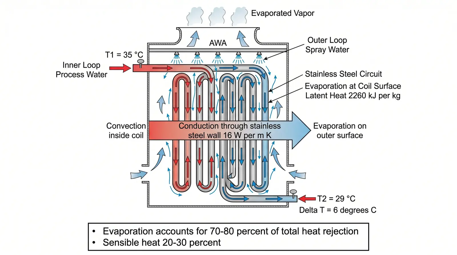
Figure 1: Dual-circuit structure of an induction furnace coil cooling system — the inner circuit for pure water circulation and the outer circuit for spray-based heat rejection through the AWA closed-circuit tower.
Problem Definition: Selection Constraints for an Induction Furnace Cooling System
The cooling system selection for an induction furnace is governed by three hard constraints:
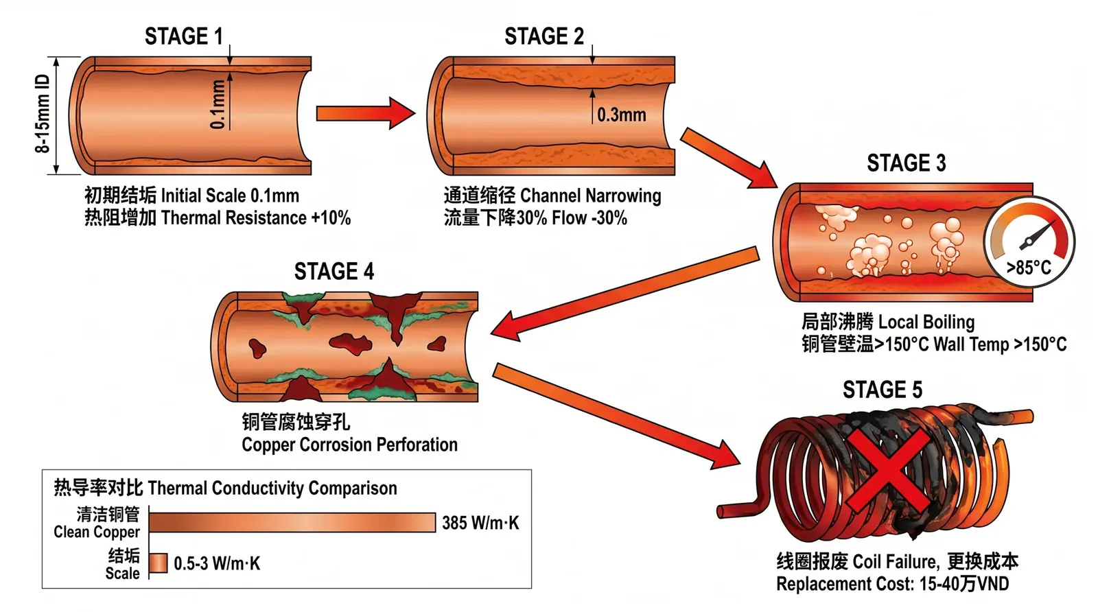
- Water quality constraint: The inner diameter of the induction coil copper tube is 8–15 mm. OEMs clearly require cooling water conductivity below 200–300 μS/cm and hardness below 50–100 mg/L as CaCO₃. Under Vietnamese water quality conditions, an open cooling tower cannot meet these requirements.
- Temperature constraint: Coil inlet water temperature is usually required to be below 35°C, and outlet water temperature below 45°C. In Vietnam, summer wet-bulb temperature is about 28–30°C. The outlet water temperature of an open tower is usually 32–38°C, leaving very little temperature margin.
- Reliability constraint: An induction furnace is usually the bottleneck equipment in a casting or forging production line. A cooling system failure directly stops the production line, and downtime losses are typically 5–20 million VND per hour.
Physical Principle: Calculating the Heat Load of an Induction Coil
The cooling heat load of an induction coil comes from two sources:
- Joule heat of the coil itself, or I²R loss: This is usually 5–8% of the rated power of the induction furnace. For a 500 kW induction furnace, coil Joule heat is about 25–40 kW.
- Furnace radiation heat transfer: The metal charge inside the furnace is at 1000–1600°C and transfers heat to the coil through radiation and convection. This accounts for about 3–5% of rated power, or 15–25 kW.
How to calculate the required cooling water flow from Joule heat and radiation heat transfer
Assume the inlet-outlet water temperature difference ΔT = 10°C, and the specific heat capacity of cooling water c = 4.18 kJ/(kg·K):
Flow rate Q = P / (c × ΔT × ρ) = 78 / (4.18 × 10 × 1.0) ≈ 1.87 m³/h ≈ 31 L/min
Considering pipeline resistance and uneven distribution, the design flow rate is set at 35 L/min.
Correcting the AWA closed-circuit tower selection heat load for Vietnamese weather conditions
AWA closed-circuit tower selection heat load = coil cooling heat load × system thermal efficiency correction factor (1.1–1.2) = 78 × 1.15 ≈ 90 kW
Under typical Vietnamese meteorological conditions, with a wet-bulb temperature of 28°C, inlet water temperature of 40°C, and outlet water temperature of 32°C, the AWA selection table indicates AWA-30, with a rated heat rejection capacity of 100 kW and an inner-circuit flow rate of 40 m³/h.
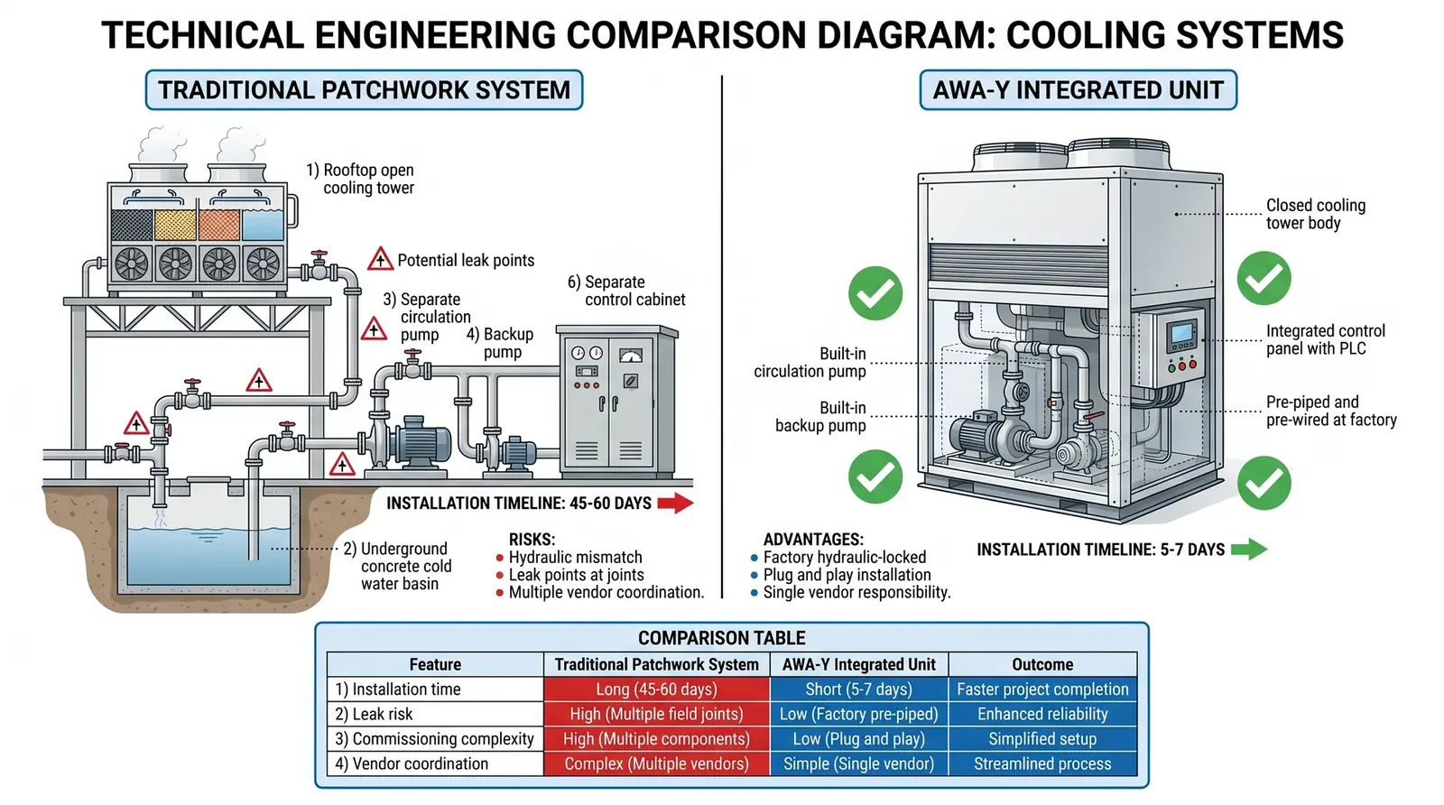
COOLTEK Solution: AWA Dual-Circuit Configuration
The standard configuration is: AWA closed-circuit tower for outer-circuit heat rejection + plate heat exchanger for heat exchange between the inner and outer circuits + inner-circuit circulating pump + water softener + corrosion and scale inhibitor dosing unit.
| Equipment | Specification | Function |
|---|---|---|
| AWA closed-circuit tower | AWA-30, heat rejection capacity 100 kW | Outer-circuit heat rejection; spray water evaporates outside the coil |
| Plate heat exchanger | Heat transfer area 2 m²; heat transfer coefficient 3000 W/(m²·K) | Heat transfer between inner and outer circuits; physical isolation |
| Inner-circuit circulating pump | Head 20 m; flow rate 35 L/min | Drives pure water circulation in the inner circuit |
| Water softener | Outlet hardness <50 mg/L | Softens make-up water for the inner circuit |
| Dosing unit | Corrosion and scale inhibitor; dosage 50–100 mg/L | Maintains stable inner-circuit water quality |
Standards Verification: Cooling Water Quality Requirements of Mainstream Induction Furnace OEMs
| Parameter | OEM Requirement (Combined) | Actual Value from Open Tower (Vietnam) | Actual Value in AWA Inner Circuit |
|---|---|---|---|
| Conductivity | <200–300 μS/cm | 800–2000 μS/cm | 150–220 μS/cm ✓ |
| Total hardness (CaCO₃) | <50–100 mg/L | 400–800 mg/L | <50 mg/L ✓ |
| pH | 7.0–8.5 | 6.5–8.0, with large fluctuations | 7.5–8.0 ✓ |
| Chloride ion | <50 mg/L | 50–150 mg/L | <20 mg/L ✓ |
Extended Questions
- If several induction coils are cooled in parallel, how should the total heat load and flow distribution be calculated when selecting an AWA tower?
- In northern Vietnam during winter, when air temperature is 5–10°C, will the AWA closed-circuit tower provide excessive cooling? How can the outlet water temperature be controlled so it does not fall below the OEM minimum requirement?
- How should the head of the inner-circuit circulating pump be calculated? How can the pressure drop of the induction coil copper tube be estimated?