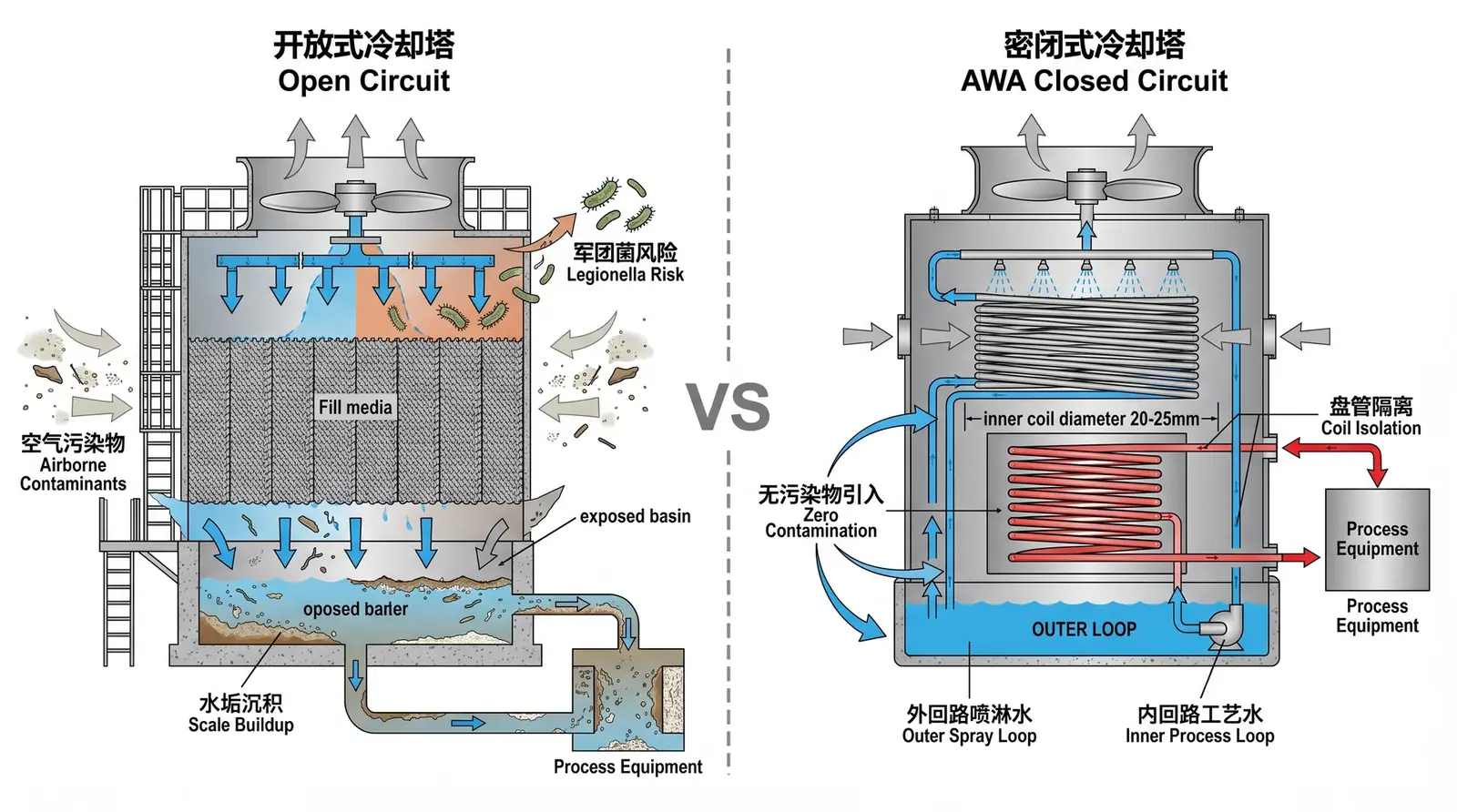
Figure 1: The thermodynamic principle of the AWA dual circuit — spray water in the outer circuit evaporates on the outside surface of the coil, with latent heat of evaporation of 2260 kJ/kg, while process water circulates in a sealed coil in the inner circuit. The two circuits transfer heat only, with no mass transfer.
Problem Definition: Why Evaporative Heat Rejection Is More Efficient Than Convective Heat Rejection
A cooling tower rejects heat in two ways: sensible heat rejection, through temperature-difference heat transfer, and latent heat rejection, through water evaporation. Under typical summer conditions in Vietnam, with dry-bulb temperature of 35°C, relative humidity of 80%, and wet-bulb temperature of about 31°C, the efficiency difference between these two heat rejection methods is very large.
- Sensible heat rejection: the temperature difference between cooling water, usually 35–40°C, and air at 35°C is extremely small, so convective heat rejection capacity is very weak.
- Latent heat rejection: the latent heat of evaporation of water is about 2430 kJ/kg at 30°C and about 2400 kJ/kg at 40°C. Evaporating 1 kg of water can remove about 2400 kJ of heat, equivalent to the heat required to raise 1 kg of water from 0°C to 573°C.
Physical Principle: Thermodynamic Analysis of the Dual Circuit
Outer Circuit: How Spray Water Forms a Film and Evaporates on the Coil Surface
The spray pump lifts spray water, usually ordinary tap water or simply treated water, to the top of the tower. It is then sprayed uniformly onto the outside surface of the coil through nozzles. The spray water forms a thin water film on the coil surface, and airflow driven by the fan, typically counterflow or crossflow, carries away the water vapor generated by evaporation.
Spray water evaporation calculation, using AWA-30 with heat rejection capacity of 100 kW as an example:
Evaporation rate = Q / L = 100 kW / 2400 kJ/kg = 0.0417 kg/s = 150 kg/h = 0.15 m³/h
This means about 150 kg of spray water evaporates per hour, requiring the same amount of fresh makeup water. Actual makeup water is slightly higher, about 1.2–1.5 times the evaporation rate, because blowdown is also required to control concentration cycles.
Inner Circuit: How Process Water Transfers Heat Only Inside the Sealed Coil
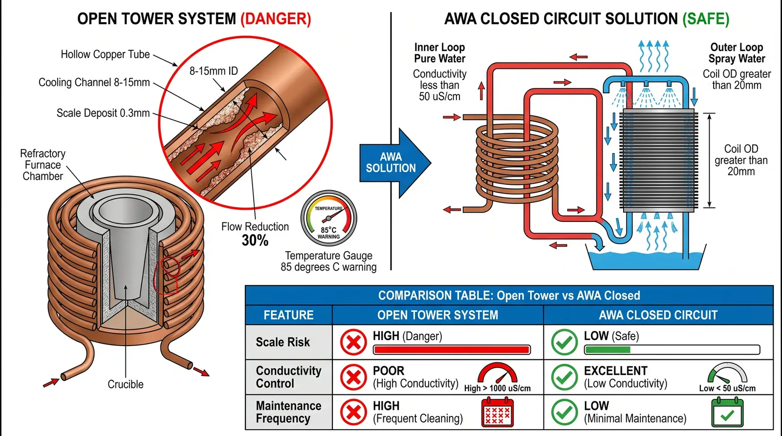
Process water circulates inside the sealed coil and transfers heat through the coil wall to the spray water film on the outside surface. The coil is typically made of hot-dip galvanized steel tube or stainless steel tube, with a tube diameter of 20–50 mm and wall thickness of 2–3 mm.
Coil heat transfer calculation, using AWA-30 as an example:
Overall heat transfer coefficient U ≈ 1000–1500 W/(m²·K), including convection inside the coil, conduction through the tube wall, and evaporative heat transfer outside the coil.
Required heat transfer area A = Q / (U × LMTD) = 100000 / (1200 × 8) ≈ 10.4 m²
The coil heat transfer area of AWA-30 is about 12 m², meeting the requirement.
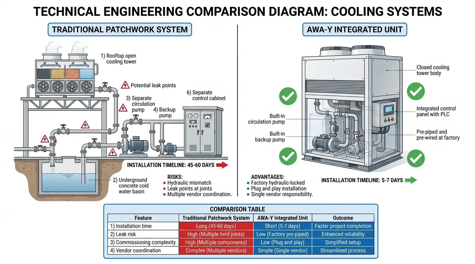
COOLTEK Solution: Engineering Implementation of AWA
The AWA series uses hot-dip galvanized steel coils as the standard option, or 304 stainless steel coils for corrosion-resistant applications. The outer surface of the coil is specially treated to enhance spray water wettability, ensuring uniform water-film coverage and avoiding dry spots, which are local areas without water film that would reduce heat transfer efficiency.
AWA uses axial-flow fans. Noise level is typically 55–65 dB(A) at a distance of 1 m, lower than an open tower of the same heat rejection capacity, which is usually 65–75 dB(A). This characteristic makes AWA especially suitable for pharmaceutical plants, food factories, and commercial buildings with noise requirements.
Transparent disclosure of the physical trade-off of AWA: the coil heat transfer efficiency of a closed-circuit tower is lower than the direct evaporative efficiency of an open tower. At the same heat rejection capacity, the volume and weight of AWA are about 1.5–2 times those of an open tower of equivalent capacity, and initial investment is about 30–50% higher. This cost is necessary in applications requiring closed-loop isolation, but for ordinary heat rejection applications without strict water-quality requirements, an open tower remains the more economical choice.Standards Verification: Heat Rejection Capacity Calculation and Meteorological Correction
The rated heat rejection capacity of AWA is usually defined under standard test conditions: inlet water temperature 40°C, outlet water temperature 32°C, and wet-bulb temperature 28°C. In actual engineering projects, correction based on local meteorological conditions is required.
| City | Summer Design Wet-Bulb Temperature | AWA Heat Rejection Capacity Correction Factor |
|---|---|---|
| Ho Chi Minh City | 28–29°C | 1.00, standard condition |
| Hanoi | 29–30°C | 0.92–0.95 |
| Da Nang | 28–29°C | 0.98–1.00 |
| Dong Nai Province | 27–28°C | 1.00–1.05 |
Extended Questions
- After scale forms on the outer surface of the AWA coil, how much will heat transfer efficiency decrease? How can outlet water temperature monitoring be used to judge whether cleaning is required?
- In winter, when wet-bulb temperature is below 15°C, AWA heat rejection capacity may greatly exceed demand. How can outlet water temperature be controlled through variable-frequency fans or spray water flow regulation?
- Does the spray water system of AWA require water treatment? If not treated, how quickly will scale form on the outer wall of the coil?