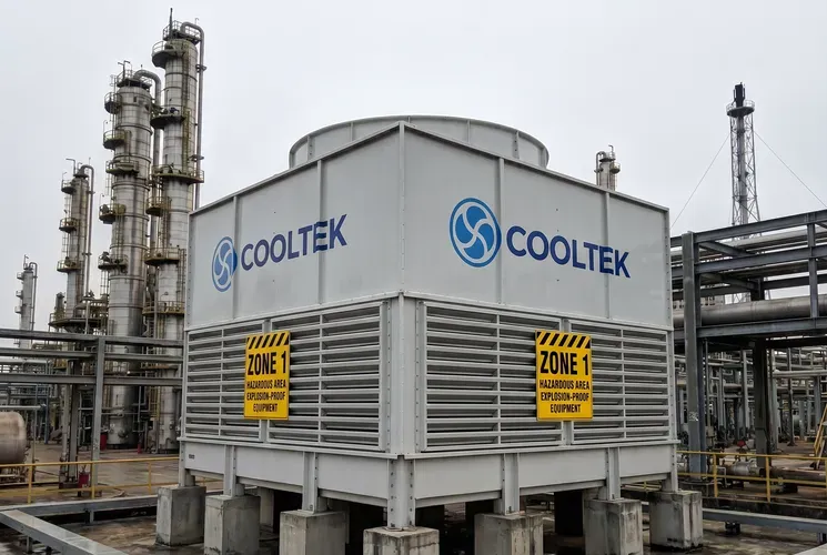
LHRD water-turbine-driven cooling tower — no electrical components on the tower top, supporting intrinsic safety in Zone 1/2 areas at the physical level.
During a cooling-system retrofit for a large petrochemical project in Vietnam, the owner originally planned to install four conventional cooling towers equipped with Ex d IIB T4 explosion-proof motors in a Zone 2 area. Eighteen months after commissioning, O&M records showed that the insulation resistance of the four explosion-proof motors, with IP66 protection, declined significantly faster than the manufacturer's reference curve in an NH₃-containing corrosive environment. Six motor replacements occurred within 18 months, equivalent to an average annual replacement rate of 1.5 times per unit. The cost per replacement, including Ex d motor purchase, high-altitude lifting and shutdown coordination, was about VND 120 million. Three of the six replacements were unplanned shutdowns, and the cumulative production-capacity loss was estimated by the project owner at more than VND 1.5 billion.
This data raises a question that must be answered at the physical level: why does an Ex d explosion-proof motor have a much higher failure probability at a cooling tower exhaust outlet than in ordinary industrial environments?
Physical Principle: The Physical Boundary of Ex d Flameproof Design
To understand this issue, the protection mechanism of an Ex d flameproof motor must first be broken down. According to IEC 60079-1, which is fully aligned with Vietnam's TCVN 10888 series, the core design logic of an Ex d flameproof motor is that the enclosure can withstand the pressure generated by an internal explosion of an explosive gas mixture and prevent the explosion from propagating into the external explosive atmosphere. In simple terms, an Ex d motor allows an explosion to occur inside the enclosure, but the enclosure must ensure that the flame is sufficiently cooled as it escapes through the joints, so it cannot ignite the external explosive gas.
This means the protection capability of an Ex d motor depends heavily on one physical condition: the integrity of the enclosure joints, or flameproof surfaces. The gap parameters of the flameproof surface, usually controlled in the range of 0.1–0.3 mm, and the surface roughness are strictly calculated and tested. Only when these parameters remain within their design values can the flame be cooled along the escape path to a temperature that is insufficient to ignite external gas.
One physical fact is easily overlooked: an Ex d motor is still, in essence, a potential ignition source. Its flameproof capability is passive protection, not active elimination. As long as circuits, windings and terminals remain inside, the risk of a short-circuit arc always exists. Ex d only ensures that even if this arc occurs, it does not propagate to the outside.
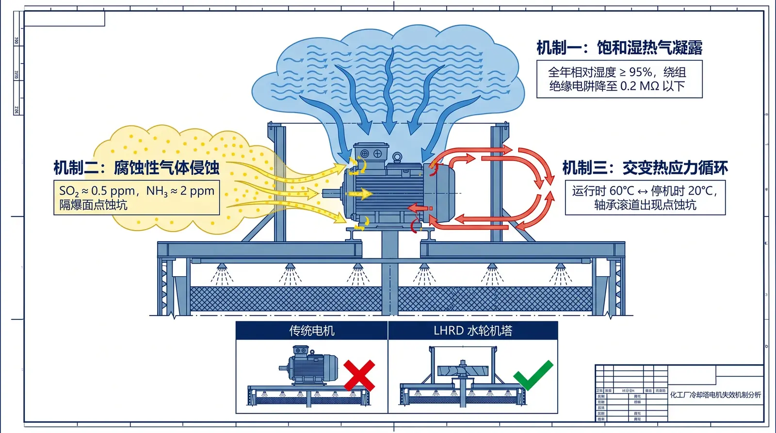
Three Failure Mechanisms at the Tower Exhaust Outlet
Mechanism 1: Saturated Vapor at 100% Relative Humidity and Continuous Condensation
The air discharged from a cooling tower after evaporative heat exchange is saturated hot and humid air, with relative humidity close to 100% and an outlet temperature usually 8–15°C higher than ambient air. When this hot humid air contacts the colder motor casing, especially after shutdown, water vapor rapidly condenses into droplets on the casing and junction-box surfaces. Condensate enters the motor through tiny gaps between shaft and end cover and through the sealing surface of the junction-box cover. Once moisture reaches the stator windings, insulation resistance begins to decline. When insulation resistance falls below 1 MΩ, the IEC 60034-1 critical value, the probability of turn-to-turn and phase-to-phase short circuits increases sharply.
Mechanism 2: Corrosive Gases Forming Acidic or Alkaline Liquid Films That Attack Flameproof Surfaces
During operation, circulating cooling water in chemical plants absorbs gases such as SO₂, H₂S and NH₃ from the air. When the gases are discharged with water vapor and condense on the motor surface, they form acidic or alkaline dilute-solution films. For an Ex d motor, the most critical damage location is the flameproof surface. The sulfurous-acid environment formed by SO₂ can corrode carbon steel and cast iron at 0.05–0.2 mm per year. Once corrosion expands the flameproof-surface gap beyond the design range, the Ex d motor loses its core protective function. Even if the outer casing appears intact, flame generated by an internal explosion may already be able to escape through the enlarged gap.
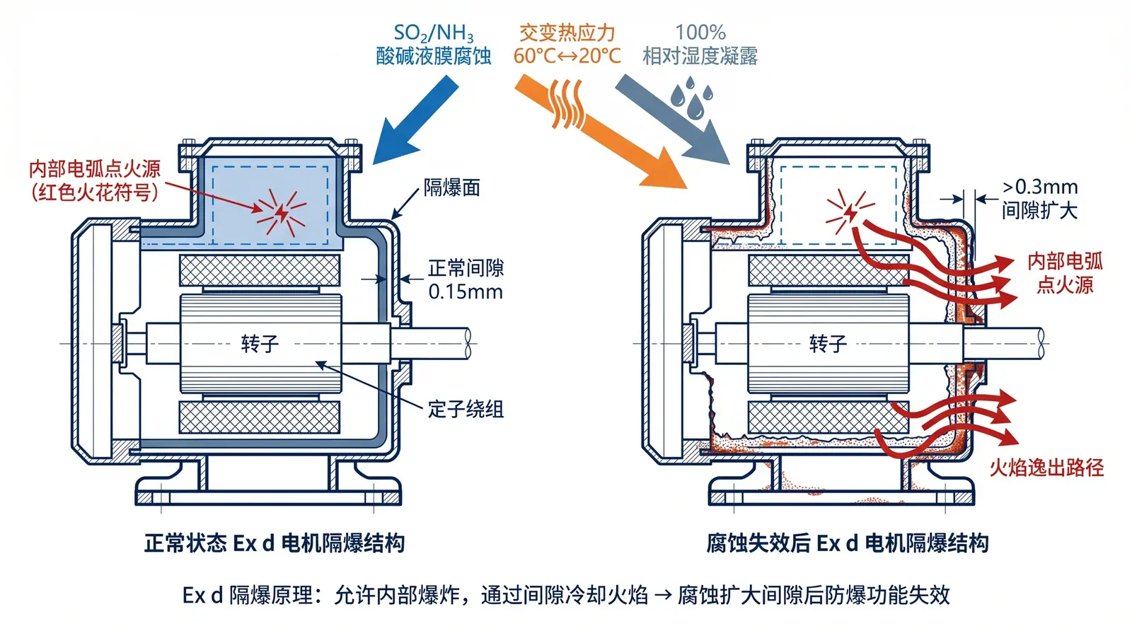
SO₂/NH₃ corrosive gases form acidic and alkaline liquid films on the motor surface, continuously attacking flameproof-surface gaps and eventually causing the explosion-proof function to fail.
Mechanism 3: Seal Aging Caused by Cyclic Thermal Stress
During motor operation, heat generated by the windings and iron core raises the internal temperature by 40–60°C. After shutdown, the humid cold air at the tower top rapidly cools the casing. This frequent thermal expansion and contraction, which may occur several times per day, imposes continuous cyclic thermal stress on seals and sealing surfaces. Seal materials gradually lose elasticity under repeated expansion and contraction, and sealing gaps gradually increase. Larger sealing gaps allow more water vapor to enter, further accelerating insulation aging and flameproof-surface corrosion. This is a self-accelerating failure cycle.
COOLTEK's Physical Solution: From "Explosion-Proof" to "No Need for Explosion-Proof Electrical Equipment"
If the root cause of motor failure is that the motor must simultaneously withstand humidity and corrosion, the alternative is not to search for a higher level of explosion-proof certification, but to physically remove the source that requires protection: the electrical components themselves. This is the design logic of the LHRD water-turbine-driven cooling tower.
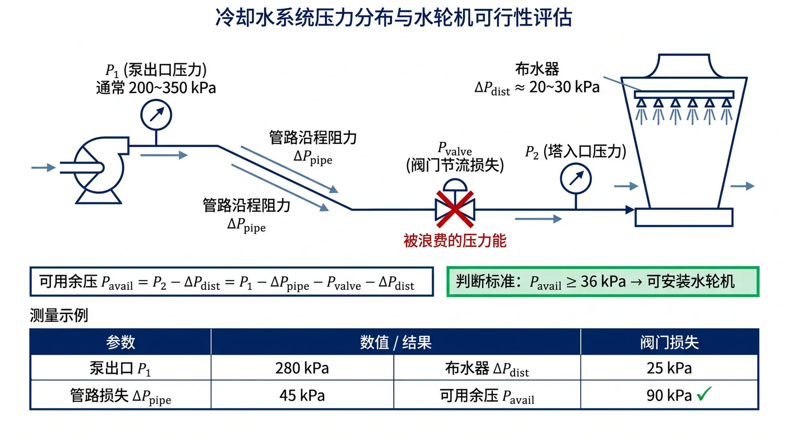
LHRD completely removes the motor, reducer, junction box and control cable from the tower top. In their place, a purely mechanical water turbine serves as the fan power source. The turbine is installed on the water-distribution pipeline inside the cooling tower and uses residual pressure from the circulating water system, at least 36 kPa, to drive the runner. The runner torque is transmitted through the main shaft to the tower-top fan, forming a complete drive chain.
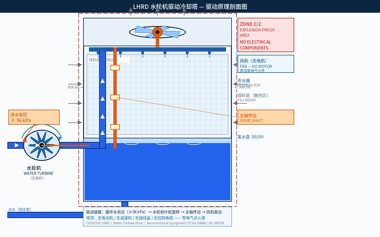
LHRD water-turbine drive principle — circulating-water residual pressure of at least 36 kPa drives the runner, and the main shaft directly drives the fan. There are no electrical components on the tower top.
In engineering terminology, this physical characteristic is called non-electrical equipment. It is fundamentally different from explosion-proof electrical equipment: it does not need to contain an explosion because there is no ignition source to begin with. In Zone 1/2 hazardous areas, this means the LHRD tower top does not need to be included in the explosion-proof electrical equipment management scope, and no Ex d certification, explosion-proof inspection or explosion-proof qualified maintenance personnel are required.
Industry-Standard Verification: 12 Months of Operating Data After Retrofit
Returning to the petrochemical project described at the beginning of this article, the retrofit method was to keep the original cooling tower body, fill and water-distribution system, and replace only the tower-top Ex d motor and reducer with an LHRD water-turbine assembly, with a turbine bypass added to the inlet piping. The retrofit was completed within a planned shutdown window, with about 48 hours of construction time per tower.
| Metric | Before retrofit, 18 months | After retrofit, 12 months |
|---|---|---|
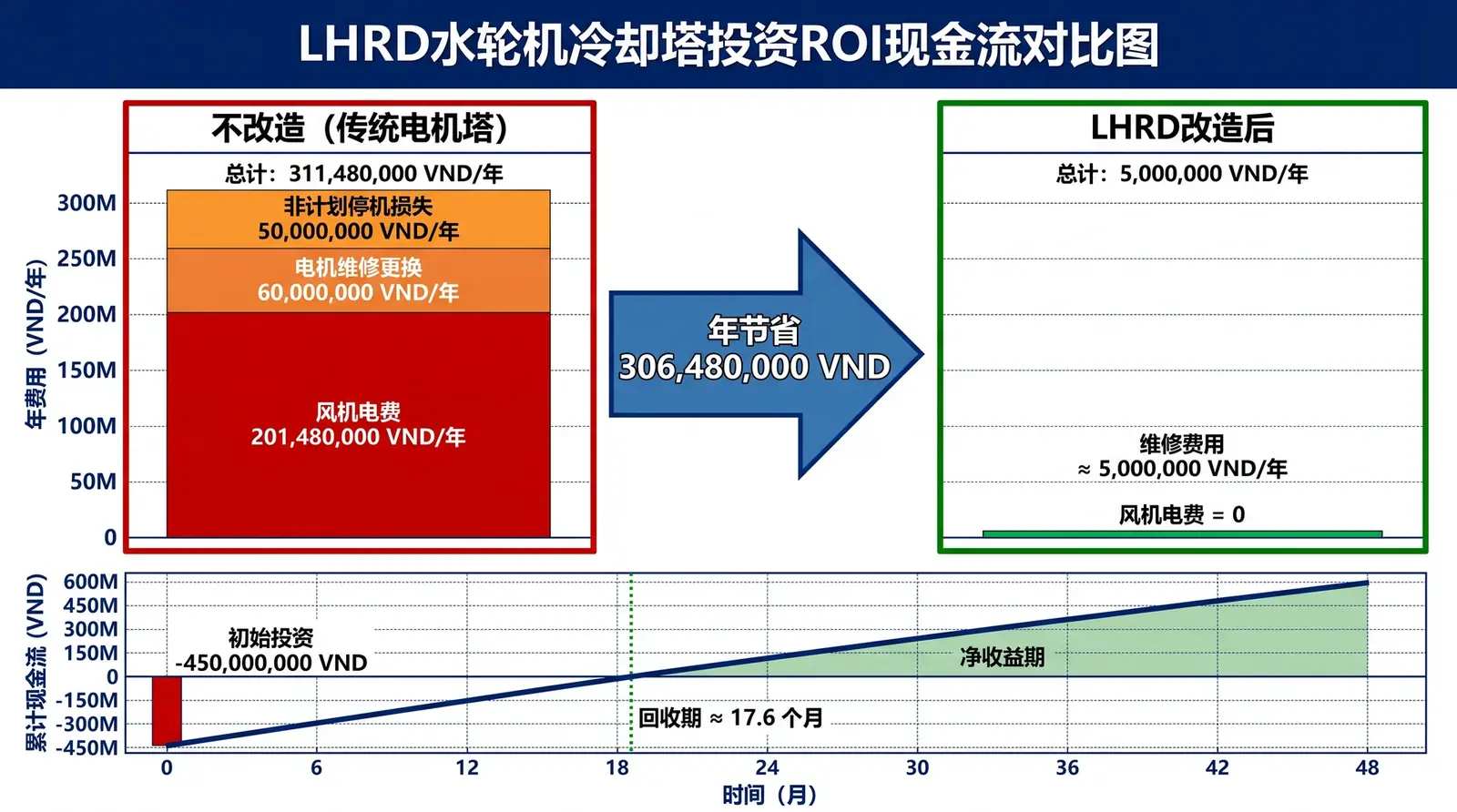
| Fan-drive electricity consumption | 4 × 22 kW = 88 kW | 0 kW |
| Motor replacements | 6 times, annual average 1.5 times per unit | 0 times |
| Unplanned shutdowns | 3 times | 0 times |
| Special explosion-proof inspection cost | About VND 20 million/year | 0, no longer applicable |
| Available residual pressure, measured | 45 kPa, valve at 60% opening | 45 kPa, turbine consumes 38 kPa |
Because the original system valve was operating at 60% opening, in throttled operation, measured available residual pressure was 45 kPa, higher than the 38 kPa required by the turbine design. The pump was not replaced. This means the entire retrofit investment can be covered by only two items: electricity-cost savings and avoided motor-replacement cost.
Extended Questions
Will the water turbine affect cooling tower heat-transfer efficiency? No. The turbine only replaces the motor as the power source and does not change the fan speed-control logic. As long as system residual pressure is at least the design value, the fan can reach rated speed and approach temperature is not affected.
What if the system does not have enough residual pressure? LHRD operation requires the system to provide at least 36 kPa of available residual pressure at the tower-top inlet flange. If residual pressure is insufficient, a higher-head circulating pump is required. Whether residual pressure is sufficient must be determined by field measurement.
What maintenance does the water turbine itself require? The turbine consists of three main parts: volute, runner and bearings. Routine maintenance only requires checking bearing lubrication every six months, with about 0.5 person-day per inspection. Unlike Ex d motors, which require explosion-proof-qualified technicians to open and inspect them, routine turbine maintenance can be performed by ordinary mechanical maintenance personnel.
Reference standards: IEC 60079-1: Explosive atmospheres — Equipment protection by flameproof enclosures "d"; TCVN 10888: Vietnam's national standard series aligned with IEC 60079; IEC 60034-1: Rotating electrical machines — Rating and performance; ASHRAE Handbook — HVAC Systems and Equipment, Chapter 40.