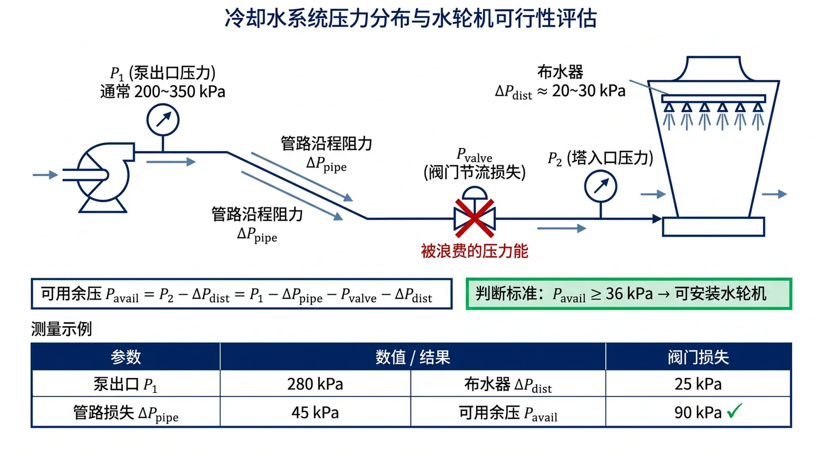
Figure 1: Schematic of measuring residual pressure in a cooling system. P1 is the pump outlet pressure before valve throttling. H1 and H2 are used to calculate the static head. The remaining pressure after deducting the distributor pressure and pipeline friction loss is the available residual pressure.
Before evaluating whether a cooling tower can be retrofitted with an LHRD water turbine, the first question is not how much electricity the fan can save, but whether the cooling-water system has enough available residual pressure.
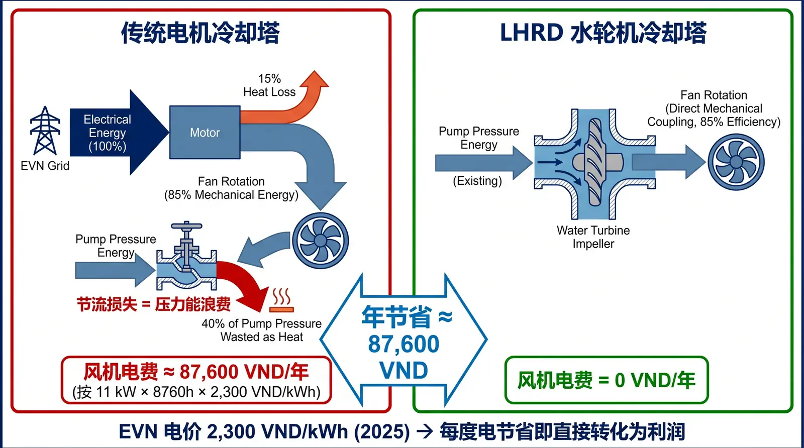
The water turbine does not generate energy. It converts the pressure energy already present in the cooling-water system into mechanical power, driving the fan to rotate. If the system has unused residual pressure, this pressure was previously consumed by the throttling valve. After the retrofit, it can be converted into fan shaft power through the water turbine. If the system has no residual pressure, the water turbine will compete with the pipeline system for pump head and may cause the cooling-water flow rate to decrease.
Therefore, on-site residual pressure measurement is the prerequisite for determining whether an LHRD retrofit is physically feasible.
Physical Principle: Where Does Residual Pressure Come From?
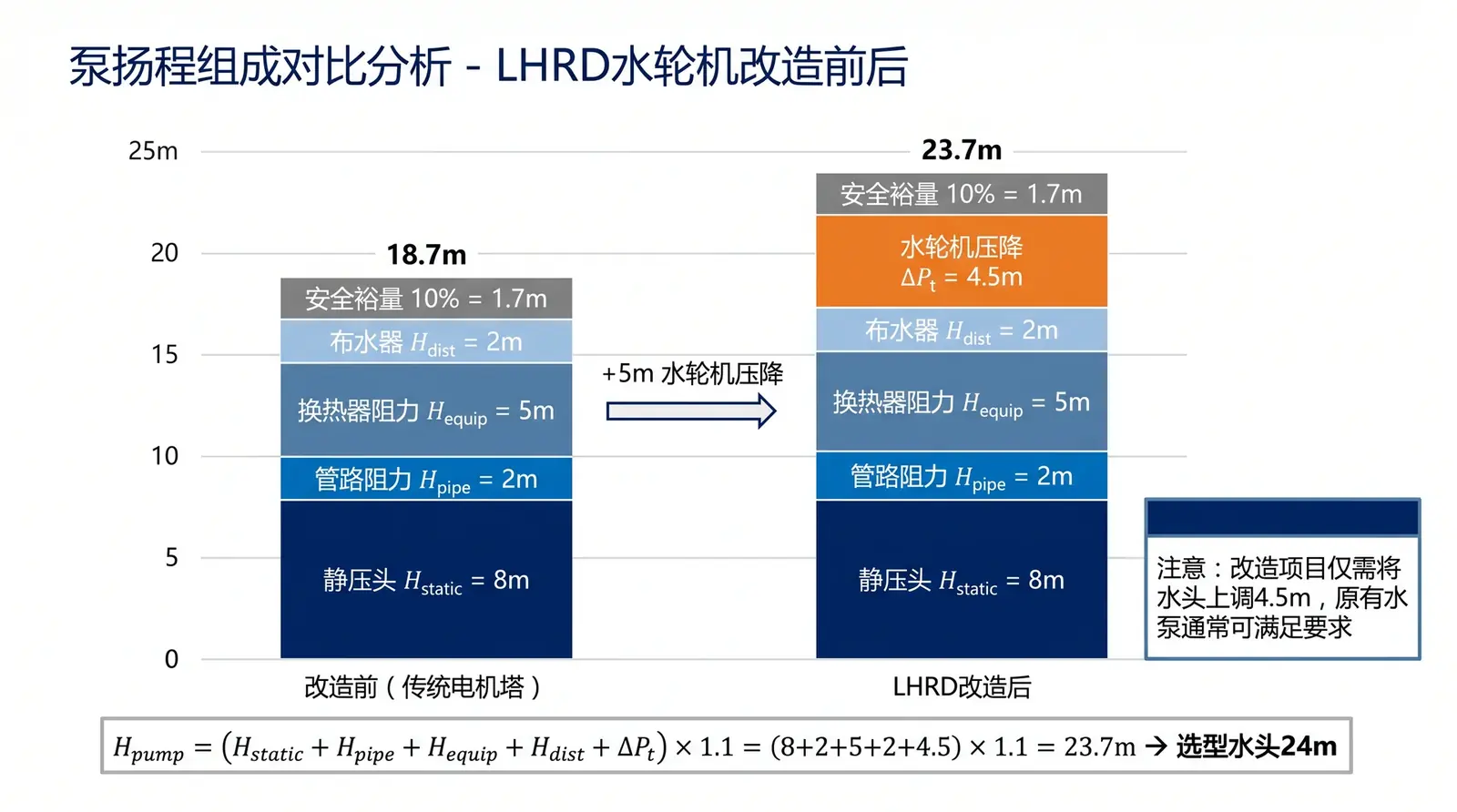
In many industrial cooling systems, pumps are selected with a safety margin. For example, when the calculated required head is 22 m, the design institute or contractor may select a 28 m pump to avoid insufficient flow. During actual operation, this surplus head is often consumed by partly closing the outlet valve.
This creates a common operating state: the pump continuously consumes extra electrical power, while part of its head is dissipated as throttling loss at the valve. For the system, this energy has no useful purpose. For an LHRD water-turbine retrofit, this is the potential pressure-energy source.
The key is to determine whether the pressure remaining before the valve, after deducting static head, distributor pressure, and pipe friction loss, is enough to drive the water turbine. According to the ASHRAE Handbook (HVAC Systems and Equipment), a safety margin of 10–20% is standard practice in pump selection, which means residual pressure is a common condition in existing systems.
Three-Step On-Site Measurement Method
Measuring residual pressure on site does not require complex instruments. A reliable pressure gauge — a Bourdon tube pressure gauge with Class 1.6 accuracy — together with a tape measure for elevation, is sufficient.
Step 1: Select the Measurement Point
On the cooling tower inlet pipe near ground level, find the pressure gauge tapping point after the pump outlet and before the valve. The pressure measured at this position is the pressure delivered by the pump before throttling. Also measure the elevation difference H2 − H1 between the measurement point and the tower-top water distributor. Since water loses about 9.8 kPa of pressure potential energy for every 1 m of vertical lift, this static head must be deducted from the total pressure.
Step 2: Read the Pressure Value
During normal system operation — the pump running at full speed, the valve at its usual throttling opening, and the cooling tower distributing water normally — read the pressure gauge value P1 in kPa. Note that P1 must be the value before the valve. If the pressure gauge is installed after the throttled valve, the pressure has already been consumed by the valve and cannot be used to calculate residual pressure.
Step 3: Calculate Available Residual Pressure
The formula for available residual pressure is:
Available residual pressure = P1 − (H2 − H1) × 9.8 − rated distributor pressure − pipe friction loss
Pipe friction loss depends on pipe length, pipe diameter, flow velocity, and pipe wall roughness. Depending on system size, it is usually in the range of 5–15 kPa.
Practical example: Suppose the following data are measured at a factory: P1 = 120 kPa, H1 = 0 m (ground level), H2 = 5 m (tower top), rated distributor pressure = 20 kPa, estimated pipe friction loss = 5 kPa. Available residual pressure = 120 − (5 − 0) × 9.8 − 20 − 5 = 120 − 49 − 20 − 5 = 46 kPa. Since 46 kPa ≥ 36 kPa, the system has the physical prerequisite for installing an LHRD water turbine.
Interpretation of Results and Next Steps
| Measured Available Residual Pressure | Interpretation | Recommended Action |
|---|---|---|
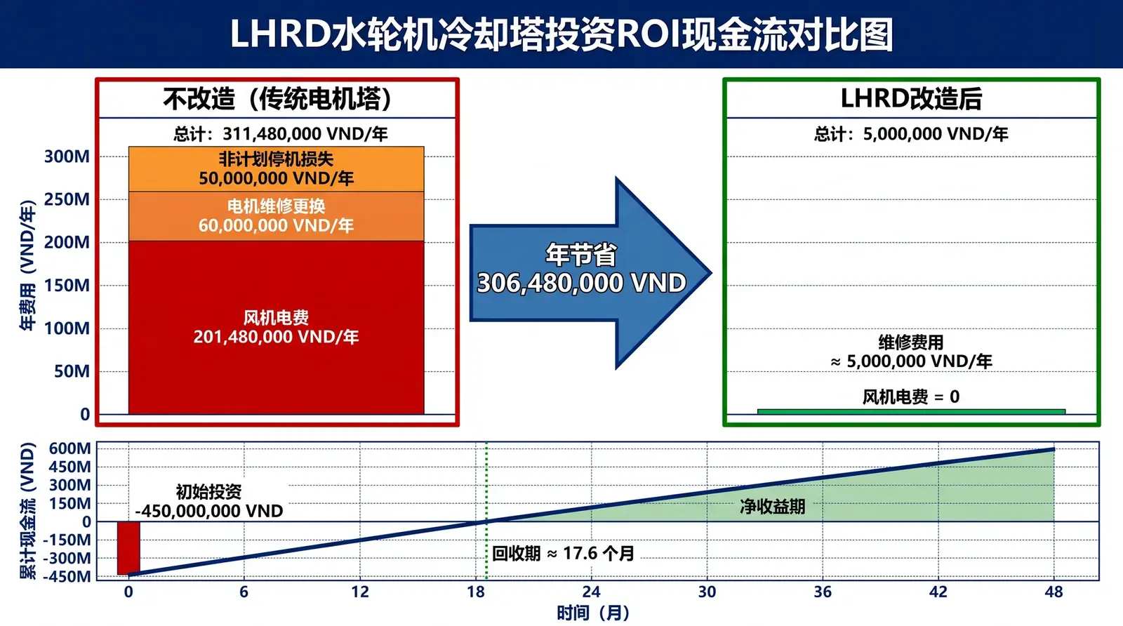
| ≥ 36 kPa | System has sufficient residual pressure | Proceed to LHRD selection and ROI calculation |
| 20–36 kPa | Marginal — borderline case | Evaluate pump replacement (add 4–5 m head); ROI likely still valid |
| < 20 kPa | Insufficient residual pressure | Consider LHR crossflow tower to reduce pump load first |
Reference standards: ASHRAE Handbook — HVAC Systems and Equipment, Chapter 40; ISO 50001: Energy Management Systems; IEC 60034-30-1: Efficiency Classes for AC Motors.