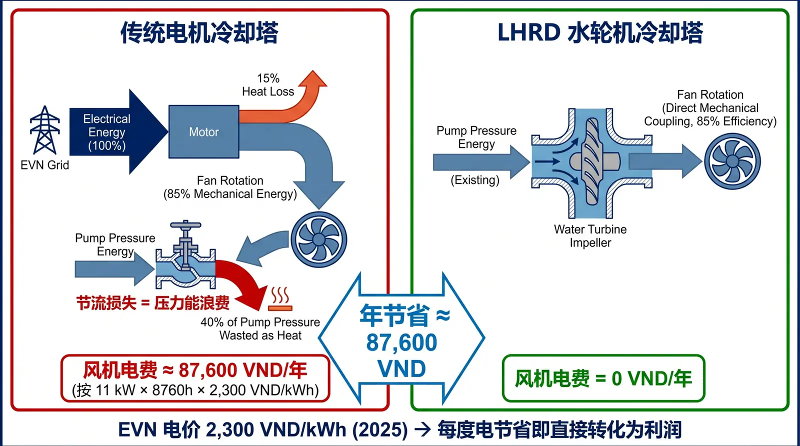
Figure 1: Energy flow comparison. In a conventional tower, throttling pressure energy wasted by the valve is directly converted by the water turbine in LHRD into mechanical work for the fan, achieving zero fan electricity consumption.
In May 2025, EVN (Vietnam Electricity) announced that the average retail electricity price would increase by 4.8% to 2,204 VND/kWh. This marked the third consecutive year of industrial electricity price increases in Vietnam. For energy-intensive industries such as paper, steel, and chemicals, the cooling water system typically accounts for 15%–25% of total plant electricity consumption. Taking a medium-sized factory with annual electricity consumption of 10 million kWh as an example, the cooling water system alone may consume about 1.5–2.5 million kWh per year. Among these loads, the fan motor on top of the cooling tower is an important contributor.
After conventional electrical energy-saving measures such as variable-frequency drive retrofits and high-efficiency motor replacement have been widely adopted, further efficiency improvement requires a system-level review of the energy flow path. In a cooling water system, there is one energy carrier that has long been overlooked: the pressure energy of circulating water. In many existing systems, part of this pressure energy is consumed through valve throttling. Water-turbine technology can convert it into mechanical work to rotate the fan, thereby reducing fan electricity consumption to zero.
Physical Principle: Pressure Energy Waste in Circulating Water Systems
The operating logic of a cooling water system is that the circulating water pump provides the driving force to deliver cooled water from the collection basin to the water distribution system at the top of the cooling tower. In this process, the pump must overcome three types of resistance: static head (the height difference that water must be lifted from low to high), pipe friction and local resistance losses from elbows and valves, and the operating pressure of the cooling tower water distributor.
When design institutes calculate pump head, they add a safety margin of 10%–20% on top of the sum of these three resistance items. According to the guidance principles in the ASHRAE Handbook (HVAC Systems and Equipment), this margin is intended to handle unforeseen factors such as pipe aging and fouling, filter blockage, and possible future piping modifications. In actual operation, however, especially during the early commissioning period or when actual piping is smoother than the design value, this safety margin does not disappear automatically. It becomes excess pressure at the pump outlet — what is known as "residual pressure."
To consume this excess pressure and prevent high-velocity water from impacting the distribution system and causing overflow or uneven distribution, operators typically partially close the pump outlet valve, keeping it at 60%–80% opening. From a fluid mechanics perspective, this partially closed valve is an artificially created throttling element. As fluid passes through the throttle, pressure energy drops sharply and is converted into heat and turbulent kinetic energy — this energy performs no useful work and is completely wasted.
COOLTEK's Physical Solution: Using Wasted Pressure to Replace Fan Motors
The LHRD water-turbine-driven cooling tower is designed based on this fluid mechanics principle. It replaces the tower-top motor and reducer with a purely mechanical water turbine. In the LHRD system, before circulating water enters the water distributor, it first passes through the turbine runner. Water enters the volute at high pressure, strikes the runner to generate torque, drives the main shaft to rotate, and then drives the tower-top fan through a coupling or direct connection. After performing work, the low-pressure water continues into the distribution system for heat exchange. The entire drive process involves no electrical power.
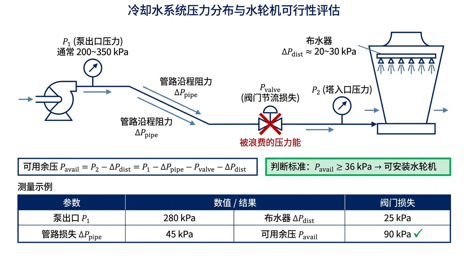
To drive the LHRD water turbine, the system typically needs to provide available residual pressure of at least 36 kPa (about 3.6 m water column). This threshold is derived by back-calculating from the turbine shaft power formula: for most industrial cooling tower configurations, the fan shaft power required is in the range of tens of kilowatts, while circulating water flow is typically hundreds to over a thousand m³/h. Combined with turbine efficiency, the minimum required working pressure drop falls in the range of 36–54 kPa. Whether this residual pressure exists in the system must be confirmed by field measurement — see the article on how to measure hidden available residual pressure for detailed steps.
Engineering Example: Annual Electricity Cost Comparison
The following example illustrates the economic effect. Consider a medium-sized steel plant cooling system: 4 cooling towers at 1,000 m³/h each, each equipped with a 30 kW fan motor. The plant operates 24/7 with 8,000 annual operating hours. EVN average electricity price is 2,204 VND/kWh. Assuming an average load rate of 85%:
| Item | Conventional Motor Tower | LHRD Water-Turbine Tower |
|---|---|---|
| Total fan power | 30 kW × 4 = 120 kW | 0 kW |
| Average operating power | 120 × 85% = 102 kW | 0 kW |
| Annual electricity consumption | 102 × 8,000 = 816,000 kWh | 0 kWh |
| Annual electricity cost | ≈ 1,798 million VND | 0 VND |
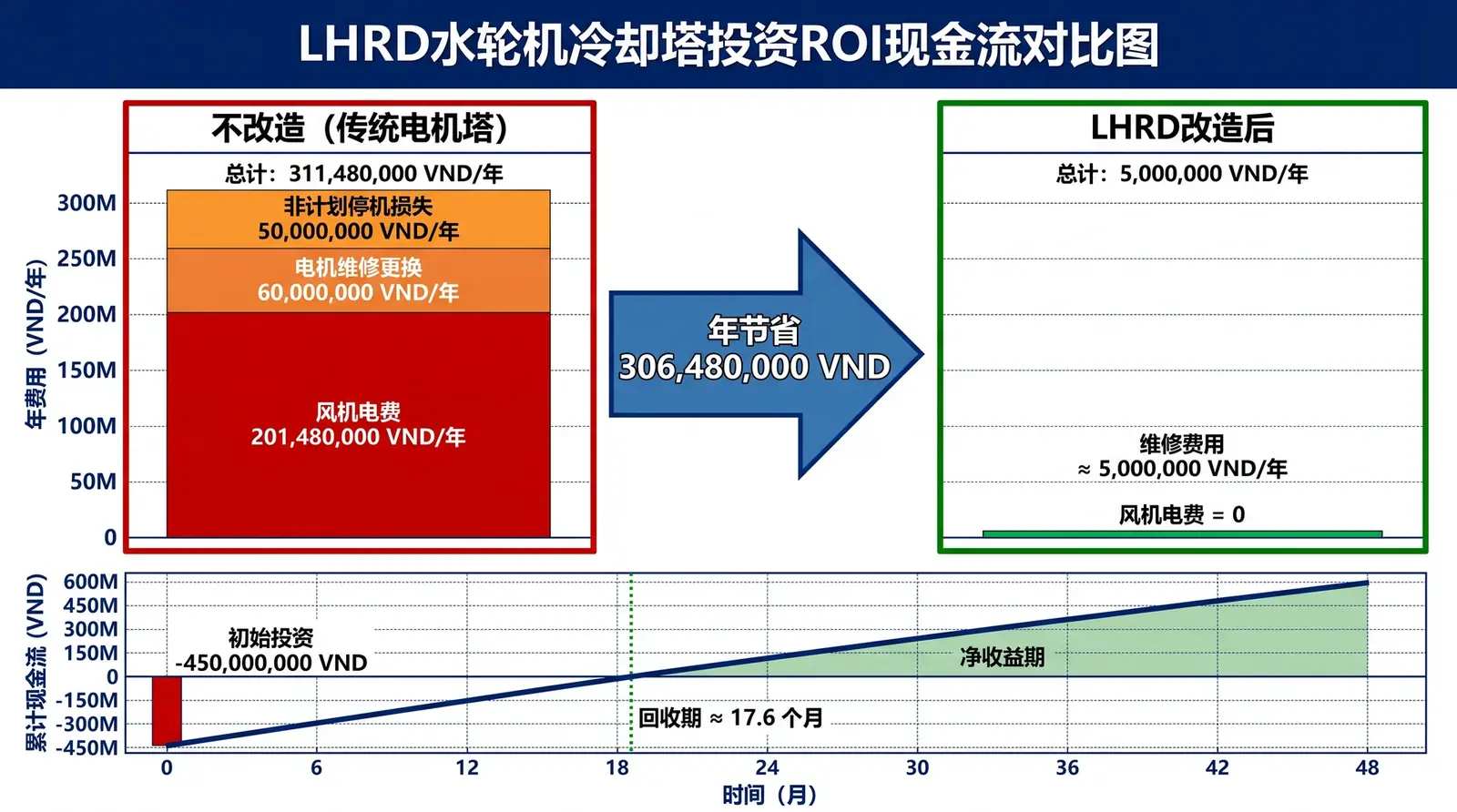
Scenario A (sufficient residual pressure): Measured available residual pressure is 45 kPa, greater than the turbine design requirement. The existing pump is retained. Annual fan electricity savings: 1,798 million VND. Retrofit investment (turbine replacement only, no pump replacement): about 500 million VND. Simple payback period = 500 / 1,798 ≈ 0.28 years (about 3.4 months).
Scenario B (insufficient residual pressure, pump replacement required): The existing pump outlet valve is fully open, with no available residual pressure. A higher-head pump adding 4 m of head is required. Total investment increases to about 700 million VND. After retrofit, additional pump power is about 54.4 kW. Annual additional pump electricity cost ≈ 959 million VND. Net annual savings = 1,798 − 959 = 839 million VND. Payback period = 700 / 839 ≈ 0.83 years (about 10 months).
Long-Term Value and Standards Compliance
Under the ISO 50001 energy management system framework, the energy-saving benefit of the LHRD solution is measurable, verifiable, and reportable. The fan changes from an electricity-consuming device to a zero-electricity device, directly reflected in energy reviews and energy baseline updates. For export-oriented enterprises facing the gradual implementation of the EU Carbon Border Adjustment Mechanism (CBAM), every percentage point reduction in electricity consumption means a reduction in Scope 2 items in carbon emission reports — a fan with zero electricity consumption corresponds to zero indirect carbon emissions.
Reference standards: ISO 50001: Energy Management Systems; ASHRAE Handbook — HVAC Systems and Equipment, Chapter 40; EVN Circular 25/2023/TT-BCT on electricity tariff structure.