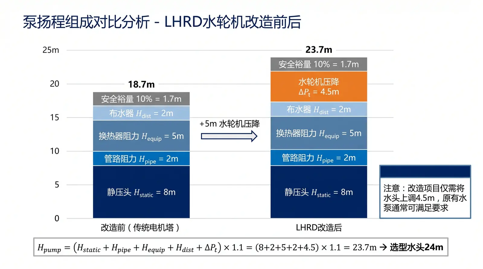
Figure 1: Comparison of pump-head components. H_pump = (H_static + H_pipe + H_equip + H_dist + ΔPt) × 1.1. The water turbine adds only 4–5 m of head requirement, while eliminating all fan electricity consumption.
When presenting an LHRD water-turbine-driven cooling tower to a design institute or EPC contractor, the most common technical question is: "Since the water turbine is driven by water pressure, it must increase pipeline resistance. How should the pump head be recalculated?"
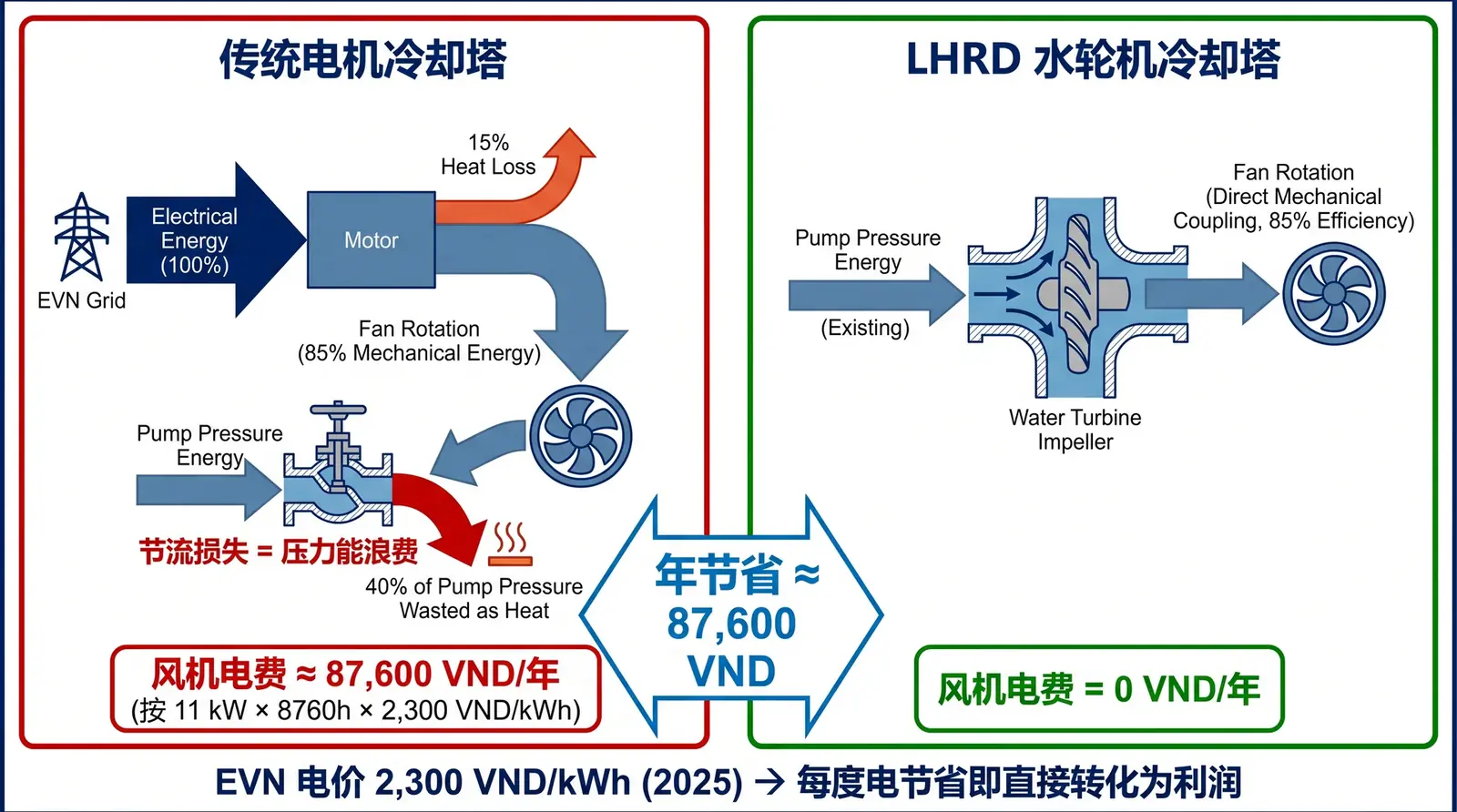
This is the right question. A water turbine is essentially an energy-conversion device. It converts the pressure energy of the fluid into mechanical energy for the fan. According to the law of energy conservation, the pressure energy consumed in this process must appear as head loss in the piping system. If pump head is calculated incorrectly, the turbine may fail to reach its required speed and air volume; in severe cases, the flow rate of the entire cooling system may drop sharply, triggering high-temperature alarms in process equipment.
Physical Principle: Where Does Turbine Resistance Come From?
In a conventional motor-driven cooling tower, such as an LHN counterflow tower or an LHR crossflow tower, the resistance imposed on the pump by the cooling tower mainly consists of two parts: static head, which is the height difference between the basin and the top water-distribution pipe, usually 3–6 m; and distribution pressure, which is the pressure required for water to pass through nozzles or the bottom holes of gravity troughs, usually 15–25 kPa, or about 1.5–2.5 m of water column.
In an LHRD water-turbine tower, before entering the water distributor, the water flow must first strike the turbine runner and perform work. In fluid mechanics, this work process appears as the pressure difference between turbine inlet and outlet, known as the turbine working pressure drop, ΔPt.
According to Bernoulli's equation, the turbine output shaft power P_shaft is proportional to flow rate Q and working pressure drop ΔPt:
P_shaft = (Q × ΔPt × η) / 3600
Here η is the turbine conversion efficiency, usually 65–80%. To drive the fan to its design speed, the turbine must output a specified shaft power. This determines, in reverse, how much pressure drop it must consume. In COOLTEK's standard design, ΔPt is usually between 3.6 and 5.0 m of water column, or 36–50 kPa.
Engineer's Practice: Pump-Head Calculation Formula
Scenario 1: New Project, Selected from Zero
For a new project, the complete pump-head calculation formula is:
H_pump = (H_static + H_pipe + H_equip + H_dist + ΔPt) × (1 + H_margin)
| Parameter | Meaning | Typical value |
|---|---|---|
| H_static | Static height difference between the highest and lowest points of the system | 3–6 m |
| H_pipe | Pipe friction loss and local losses from elbows, valves and similar fittings | 2–6 m, calculated by actual layout |
| H_equip | Water-side resistance of chiller condenser or process heat exchanger | 4–8 m, provided by equipment supplier |
| H_dist | Cooling-tower distributor working pressure | 1.5–2.5 m |
| ΔPt | Turbine working pressure drop, calculated and matched by COOLTEK | 3.6–5.0 m |
| H_margin | Safety margin | 10% |
Conclusion: in a new project using an LHRD tower, only 4–5 m of additional head needs to be added to the conventional pump-head calculation. The electricity consumed by this additional 4–5 m of pump head is far lower than the fan-motor electricity that is eliminated.
Scenario 2: Existing-Plant Retrofit Using the Current Pump
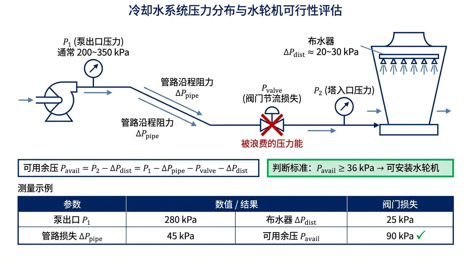
For an existing-plant retrofit, replacing an expensive large pump is usually not preferred. The core task is to assess whether the existing system has enough "hidden residual pressure." The evaluation formula is:
Available residual pressure = actual operating head of existing pump − (H_static + H_pipe + H_equip + H_dist)
If the calculated available residual pressure is at least 4 m of water column, or 40 kPa, the pump does not need to be replaced. The motor can be removed and replaced directly with the water turbine. For the specific measurement method, refer to the article on how to measure hidden available residual pressure in the system.
Industry-Standard Verification: The Optimum Solution for System Efficiency
Is it worthwhile to increase pump head in order to drive the fan? According to efficiency data for pumps and fans in ASHRAE 90.1, a high-quality centrifugal pump usually has an efficiency of 75–85%, while the combined efficiency of a cooling tower fan drive system, including motor, reducer and belt, is often only 55–65%.
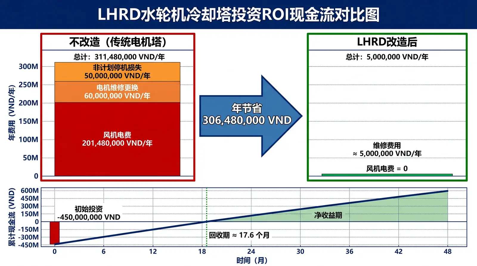
Using a high-efficiency pump to perform work centrally, and replacing lower-efficiency distributed fan drive work, is favorable both thermodynamically and economically. Taking a 500 m³/h cooling tower as an example, the additional pump shaft power caused by the turbine is about 6–8 kW, while the fan power eliminated is usually 15–30 kW. Net energy saving is therefore about 9–22 kW.
Extended Questions
Is the pressure drop of a water turbine fixed? No. Turbine pressure drop changes with water flow rate; the higher the flow rate, the higher the pressure drop. In variable-flow systems, such as multiple pumps in parallel or partial-load operation with only some pumps running, it is necessary to check whether the pressure drop under the minimum-flow condition can still drive the fan to the required speed.
What if an additional 5 m of head causes the pump motor to overload? If the existing pump motor has insufficient power margin, forcibly adding resistance may cause overload. In that case, the pump motor must be replaced with a higher-power unit, or the water-turbine solution should be abandoned and a low-resistance LHR crossflow tower should be used instead; its head loss is 4–6 kPa lower than that of a counterflow tower.
If the system has no residual pressure, what low-energy options remain? If residual pressure is insufficient and pump replacement is not planned, consider using a low-head-loss crossflow tower to reduce long-term pump load, or retaining the conventional motor-driven solution while using IE4/IE5 high-efficiency motors with variable-frequency control to optimize part-load electricity consumption.
Reference standards: ASHRAE 90.1: Energy Standard for Buildings Except Low-Rise Residential Buildings; ISO 9906: Rotodynamic pumps — Hydraulic performance acceptance tests; CTI STD-201: Standard for the Certification of Water-Cooling Tower Thermal Performance.