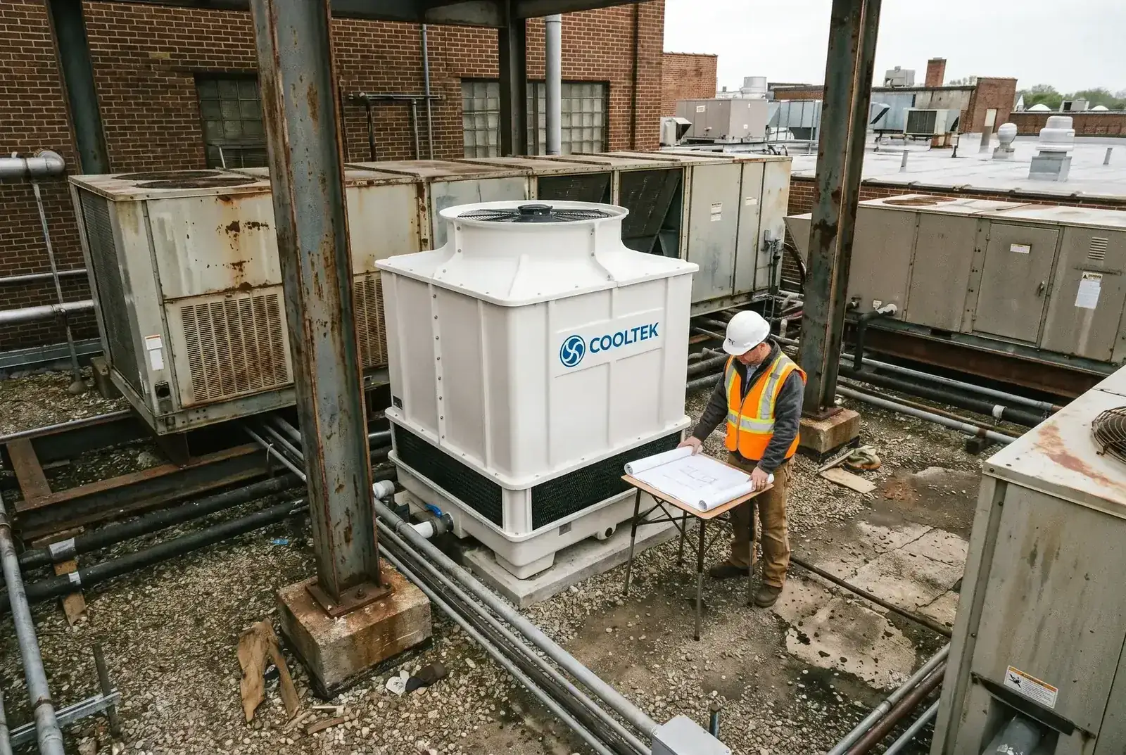
Figure 1: The difference in piping topology between a single central inlet and a dual-side inlet directly determines the complexity of retrofit work and the required shutdown time.
At 10 p.m. on a Friday, the industrial park has quieted down, but the equipment department of a large injection molding plant is still brightly lit. The plant manager has issued a firm order: the replacement of two old rooftop cooling towers must be completed within the 48-hour weekend shutdown window, and the production line must restart on time at 8 a.m. Monday.
Equipment supervisor Li originally thought this would be a routine lifting job. But when the newly purchased crossflow cooling tower is placed on the roof, he is stunned. The existing main inlet pipe is a straight pipe, while the new tower uses a dual-side inlet structure that requires one pipe connection on each side of the tower. This means the team must drain the entire piping network overnight, cut the main pipe, weld on a large Y-shaped tee branch, and then route two curved branch pipes through a narrow equipment gap.
By late Sunday night, welding is still underway, and pressure testing of the piping system is nowhere near completion. Li knows the Monday morning restart is no longer possible. In this race against time, Li made a critical mistake: he focused entirely on comparing the heat-rejection parameters of the cooling tower, but ignored one construction detail that can be decisive on site — the inlet piping configuration.
Physical Principle: The Geometric Constraint of Piping Topology
Why do some cooling towers require two inlet pipes, while others need only one? This is determined by the internal air-water contact structure of the cooling tower.
In a crossflow cooling tower, such as the LHR Series, the fill must be arranged on the left and right sides of the tower to allow air to pass horizontally through it, while the central space is kept open as the fan suction chamber. This "sandwich" structure determines that hot water must be evenly distributed into top water basins on both sides. Therefore, at the physical level, a crossflow tower requires the main inlet pipe to make a symmetrical branch, using a Y-shaped or T-shaped configuration, before entering the tower, forming a dual-side inlet piping topology.
This symmetrical branching not only increases piping material cost; more critically, it consumes a large amount of site construction space and time. In old-factory retrofits, existing piping is often fixed in place. Forcing a symmetrical pipe network into a narrow space can become extremely difficult.
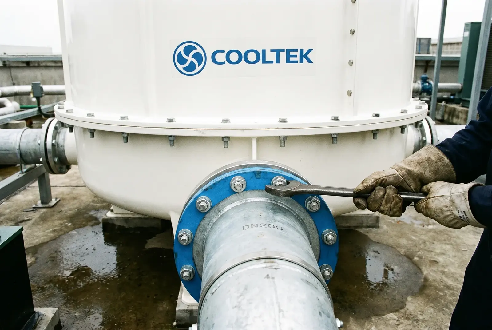
By contrast, in a counterflow cooling tower such as the LHN Series, the fill is concentrated in the central tower body. Hot water only needs to enter the top water distribution system through one main inlet pipe located on the tower centerline, and then it is uniformly sprayed over the fill surface through pressurized nozzles. This single central inlet design eliminates the physical need for symmetrical branching and simplifies a complex "one-to-two" pipe network into the most direct "point-to-point" connection.
COOLTEK's Physical Solution: Recovering Shutdown Time with a Simplified Topology
First: Compress Shutdown Time as Much as Possible
If Li had selected an LHN counterflow square tower, the outcome would have been very different. The LHN can connect directly to the existing main water pipe on one side. The inlet-pipe connection can be completed in parallel with tower lifting. The entire retrofit process can be compressed into the 48-hour weekend window, allowing the production line to restart on time Monday morning.
Second: Operate Within Extremely Small Spaces
A crossflow tower with a dual-side inlet not only has a larger footprint; it also requires at least 500–800 mm of piping operation and maintenance space on each side. The LHN's single central inlet design requires only one piping connection point at the front or rear of the tower and places no requirement on the side space. Combined with the LHN's square minimum-footprint advantage, such as only 25.00 m² at a flow rate of 500 m³/h, this allows the LHN to fit into extremely space-limited scenarios where a crossflow tower cannot be installed, including wall-side installation.
Third: A Maintenance Benefit Over 15 Years
A single central inlet piping system is simple in structure, with fewer valves and more concentrated inspection points. Over a 15–20 year lifecycle, this simplified topology brings meaningful maintenance benefits. During routine inspection and troubleshooting, engineers only need to check one inlet point and one main valve, rather than moving back and forth on both sides of the tower and spending effort balancing the water flow of two side basins.
Industry Standard Verification: Transparent Disclosure of Engineering Trade-Offs
According to ISO 13706, Petroleum, petrochemical and natural gas industries — Air-cooled heat exchangers, and related fluid-transport principles, piping systems should, while meeting flow requirements, simplify piping topology as much as possible and reduce the number of elbows, branches, and valves in order to reduce head loss, leakage risk, and maintenance complexity. The LHN single central inlet design is an appropriate implementation of this engineering principle.
However, as a responsible engineering advisor, we must proactively disclose the physical trade-off of the LHN counterflow structure. Because it uses a pressurized nozzle water distribution system, the LHN Series has a water head loss, usually 40–55 kPa, higher than that of the LHR crossflow series with gravity basin water distribution, usually 36–52 kPa. This means that although you gain advantages in retrofit construction and footprint, you may need to select a circulating water pump with a slightly higher head.
| Comparison Dimension | LHN Single Central Inlet | LHR Dual-Side Inlet |
|---|---|---|
| Number of inlet pipes | 1, simplified topology | 2, symmetrical branching |
| Additional shutdown time during retrofit | Very short, connection can proceed together with tower installation | Longer, requiring draining, cutting, and welded branching |
| Side piping operation space | No requirement; wall-side or adjacent-equipment installation possible | Must be reserved, at least 500–800 mm on each side |
| Water head loss, 500 m³/h example | 52 kPa, slightly higher pump head required | 46 kPa, lower pump energy consumption |
| Maintenance inspection points and valve quantity | 1, centralized and lower risk | 2, distributed and requiring balancing |
Reference standards: ISO 13706: Petroleum, petrochemical and natural gas industries — Air-cooled heat exchangers; ASHRAE Handbook — HVAC Systems and Equipment, Chapter 40; CTI STD-201: Standard for the Certification of Water-Cooling Tower Thermal Performance.