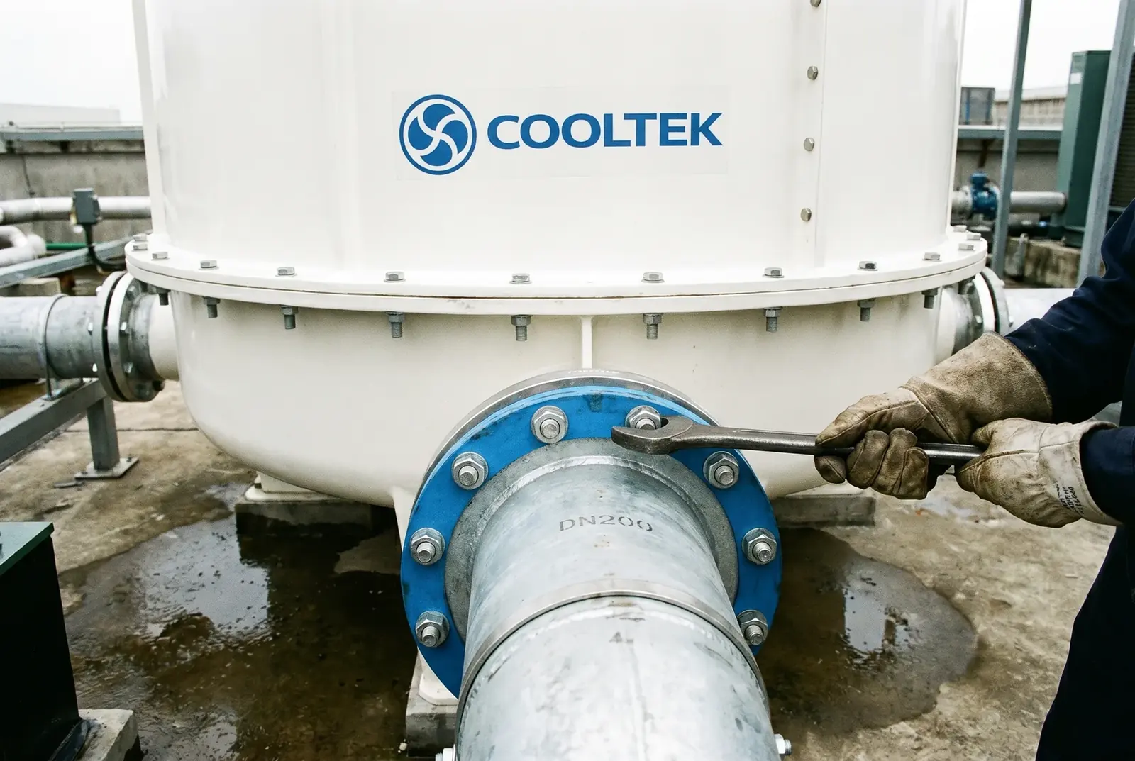
Figure 1: In old-factory expansion projects where space is already locked, selecting the right tower type is the key to reducing civil-work investment.
In an established textile factory in Binh Duong, Vietnam, the plant manager is looking at a newly signed large order from Europe and the United States and feeling worried. To fulfill this order, the factory must add two new production lines within three months. Funding is ready and the equipment has been ordered, but when the EPC contractor lays the expansion drawings on the table, everyone falls silent.
The new production lines require an additional 500 m³/h of cooling water flow, which means a large cooling tower must be added. However, after more than ten years of repeated modifications, the plant roof is already crowded with exhaust fans, outdoor air-conditioning units, and old water tanks. There is almost nowhere to stand. The contractor reluctantly explains that the only option is to apply to the industrial park for plant expansion and recast the equipment foundation — a long approval process with high civil-work cost that would directly consume most of the profit from the order.
In fact, there is a third option: select a cooling tower that can survive in the available gap.
Physical Principle: Why Do Some Cooling Towers Take Up So Much Space?
To understand why different cooling tower types have such large differences in footprint, we need to return to their internal air-water contact methods.
In a crossflow cooling tower, such as the LHR Series, air passes horizontally through the fill. To ensure that air can pass evenly through the entire fill layer, the fill is usually arranged on both sides of the tower, while a large empty chamber must be reserved in the center as the fan suction zone. This "sandwich" structure determines that the plan projection of a crossflow tower is necessarily a relatively wide rectangle, with a considerable amount of non-effective space in the middle.
In a counterflow cooling tower, such as the LHN Series, air passes vertically upward through the fill. The fill can cover almost the entire horizontal section of the tower, without wasting space on a central suction chamber. This 180° fully opposite contact not only provides the maximum thermodynamic temperature-difference driving force, but also achieves the highest geometric space utilization.
According to Chapter 40 of the ASHRAE Handbook, under the same heat-rejection capacity, the required plan area of a counterflow tower is often 20% to 30% smaller than that of a crossflow tower. In old-factory renovation projects where every square meter matters, this 20% area difference can be the boundary between "it fits" and "it cannot be installed."
COOLTEK's Physical Solution: The Three Space Advantages of LHN
First Advantage: Direct Footprint Reduction
Let us use real engineering data. Assume your expansion project requires an additional 500 m³/h of cooling water flow. If you choose an LHR crossflow square tower, model LHR-500L/MB, its foundation size is 9.12 m × 3.60 m, with a footprint of 32.83 m². If you choose an LHN counterflow square tower, model LHN-500L/SB, its foundation size is only 5.00 m × 5.00 m, with a footprint of 25.00 m².
With exactly the same cooling capacity, the LHN saves 23.8% of valuable space. The nearly 8 m² saved may allow you to avoid a structural column or eliminate the need to remove an adjacent piece of old equipment.
Figure 2: Footprint comparison at 500 m³/h — LHN 25.00 m² vs LHR 32.83 m², saving 23.8% of space.
Second Advantage: Removing Piping Dead Corners
In addition to the footprint of the tower itself, piping layout space is another hidden constraint in expansion projects. The dual-side inlet design of a crossflow tower requires at least 500–800 mm of piping operation space on both sides of the tower. The LHN Series uses a single central inlet design, where hot water enters through one main inlet pipe located along the tower centerline.
This means the sides of the LHN can be placed close to walls or adjacent equipment, and multiple LHN units can even be arranged side by side with effectively zero spacing. This simplified piping topology removes piping dead corners around the equipment and converts every available inch into actual cooling capacity.
Third Advantage: Modular Assembly Like Building Blocks
Compared with conventional round counterflow towers, the LHN Series adopts a square modular design. When round towers are installed side by side, unusable petal-shaped gaps inevitably remain between the circular bodies. The square structure of the LHN can fit the building module of the plant, such as column-grid spacing, like building blocks. Multiple LHN units can be assembled into a tight overall layout, pushing space utilization toward the physical limit.
Industry Standard Verification: Transparent Disclosure of Trade-Offs
When large equipment is added to the roof or equipment floor of an existing plant, building structural safety standards must be strictly followed. According to TCVN 2737:2023, Design Loads and Actions for Buildings and Structures, issued by Vietnam's Ministry of Construction, the wet weight of any newly added equipment must not exceed the bearing capacity of the existing building structure.
As a responsible engineering advisor, we must clearly disclose the physical trade-off of the LHN Series. Because the counterflow tower uses a denser fill arrangement and a larger bottom basin water volume, the operating weight of the LHN Series is usually slightly higher than that of a crossflow tower at the same flow rate. The wet weight of LHN-500L/SB is 9,180 kg, while that of LHR-500L/MB is 8,950 kg. In an existing plant roof operating near its bearing limit, these few hundred kilograms still require attention from a structural engineer.
In addition, the water head loss of the LHN (52 kPa) is also slightly higher than that of the LHR (46 kPa). This means that while you save significant civil-work cost, you may need to select a circulating water pump with a slightly higher head. Compared with months of plant expansion approval and high construction costs, however, this additional pump energy consumption is usually a highly acceptable trade-off.
| Comparison Dimension | LHN Counterflow Square Tower | LHR Crossflow Square Tower |
|---|---|---|
| Footprint, 500 m³/h example | 25.00 m², very small | 32.83 m², larger |
| Piping layout space requirement | None on both sides; single central inlet, wall-side installation possible | Side clearance required; dual-side inlet |
| Space utilization for multiple units | 100%, square zero-spacing arrangement | Lower, because air inlet and piping space must be reserved |
| Wet weight, 500 m³/h example | 9,180 kg, structural bearing must be checked | 8,950 kg |
| Water head loss, 500 m³/h example | 52 kPa, pump head needs to be slightly higher | 46 kPa |
Reference standards: ASHRAE Handbook — HVAC Systems and Equipment, Chapter 40; TCVN 2737:2023 Design Loads and Actions for Buildings and Structures.