When selecting a cooling tower, the choice between crossflow and counterflow configurations is one of the most consequential decisions. Both configurations can achieve the required cooling duty, but they differ significantly in noise output, water-side pressure drop, outlet temperature stability under variable load, and maintenance accessibility.
This article analyzes these four dimensions from a physics perspective to provide a structured decision framework for different industrial scenarios.
Crossflow and counterflow towers have fundamentally different air-water contact geometries, which drives differences in noise, pressure drop, temperature stability, and maintenance requirements.
1. Dimension 1: Noise Output
1.1 Noise Sources in Cooling Towers
Cooling tower noise has three main sources: fan aerodynamic noise, water impact noise (water falling onto fill or basin), and motor/gearbox mechanical noise. The relative contribution of each source differs between crossflow and counterflow configurations.
1.2 Why Crossflow Towers Are Quieter
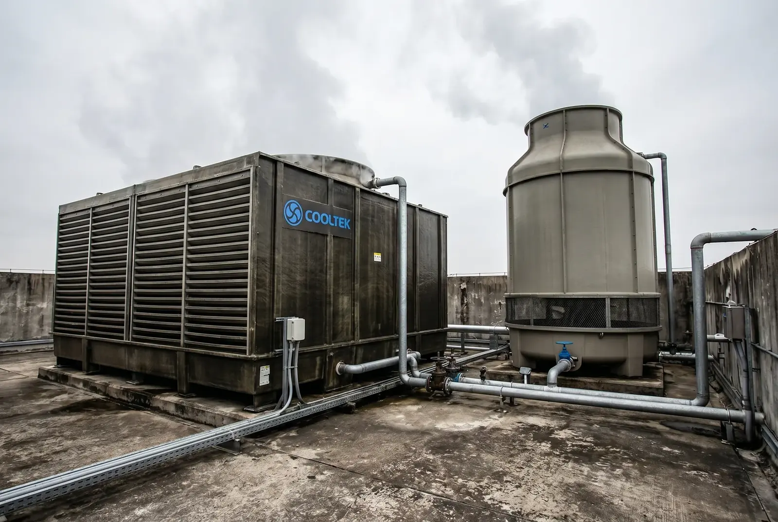
In a counterflow tower, air flows upward while water falls downward — they meet head-on. This creates higher air turbulence and greater water impact velocity at the fill surface, resulting in higher noise levels.
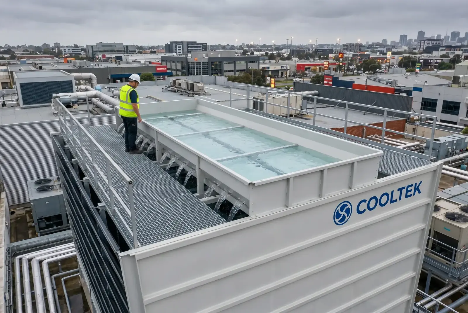
In a crossflow tower (such as the COOLTEK LHR), air flows horizontally through the fill while water falls vertically. The air-water contact is gentler, and the fan can operate at lower rotational speed for the same airflow volume because the air path resistance is lower. Typical noise comparison:
| Tower Type | Typical Sound Pressure Level (1 m) | Primary Noise Source |
|---|---|---|
| Standard counterflow (round tower) | 72–78 dB(A) | Fan + water impact |
| Square counterflow | 68–74 dB(A) | Fan + water impact |
| LHR crossflow (COOLTEK) | 52–62 dB(A) | Fan (low-speed large-diameter) |
The 10–16 dB(A) difference between LHR crossflow and standard counterflow towers is significant: a 10 dB(A) reduction corresponds to a perceived noise reduction of approximately 50%.
2. Dimension 2: Water-Side Pressure Drop
2.1 Pressure Drop Mechanism
Water-side pressure drop is the resistance that the circulating water pump must overcome to push water through the cooling tower. Higher pressure drop means higher pump energy consumption.
In a counterflow tower, water must be pumped to the top of the tower and then distributed through pressurized nozzles (typically requiring 30–50 kPa nozzle pressure). The total water-side pressure drop is typically 60–100 kPa.
In the LHR crossflow tower, water is pumped to the open gravity distribution basin at the top, then falls by gravity through the fill. The nozzle pressure requirement is zero. Total water-side pressure drop is typically 20–40 kPa.
2.2 Annual Energy Cost Impact
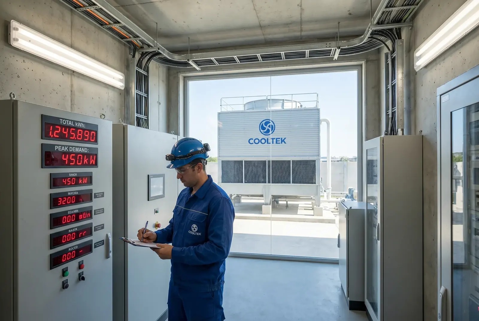
For a 500 m³/h system, reducing water-side pressure drop by 40 kPa saves approximately 15,000–20,000 kWh per year at current EVN electricity tariffs.
For a 500 m³/h cooling water system operating 8,000 hours per year, the annual pump energy savings from a 40 kPa pressure drop reduction is:
- Power reduction: 500 m³/h × 40 kPa ÷ 3,600 ÷ 0.75 (pump efficiency) ≈ 7.4 kW
- Annual energy saving: 7.4 kW × 8,000 h = 59,200 kWh
- Annual cost saving (at EVN Tier 3 rate ~2,500 VND/kWh): ~148 million VND (~6,000 USD)
3. Dimension 3: Outlet Temperature Stability
3.1 Response to Variable Load
Industrial cooling loads are rarely constant. Process equipment starts and stops, production shifts change, and seasonal ambient conditions vary. The ability to maintain stable outlet water temperature under variable load is an important selection criterion.
Counterflow towers have a steeper temperature gradient along the fill height, making them more sensitive to changes in water flow rate. When water flow drops to 60% of design, the outlet temperature can rise by 3–5°C above the design point.
Crossflow towers have a more uniform temperature distribution across the fill width, and the open basin provides a small buffer volume. When water flow drops to 60% of design, the outlet temperature typically rises by only 1–2°C above the design point.
4. Dimension 4: Maintenance Accessibility
As discussed in detail in the article on 24/7 online maintenance, the crossflow tower's open gravity basin allows all water distribution maintenance to be performed without shutdown. The fill is accessible from the side for inspection and sectional replacement. The counterflow tower's enclosed nozzle system requires full shutdown for cleaning.
| Scenario | Recommended Configuration | Key Reason |
|---|---|---|
| Noise-sensitive location (near residential, hospital) | LHR Crossflow | 10–16 dB(A) lower noise |
| High pump energy cost concern | LHR Crossflow | 40–60 kPa lower pressure drop |
| 24/7 continuous production | LHR Crossflow | Online maintenance capability |
| Very high wet-bulb approach required (<3°C) | Counterflow | Higher NTU per unit volume |
| Tight footprint, height not constrained | Counterflow | Smaller plan area |
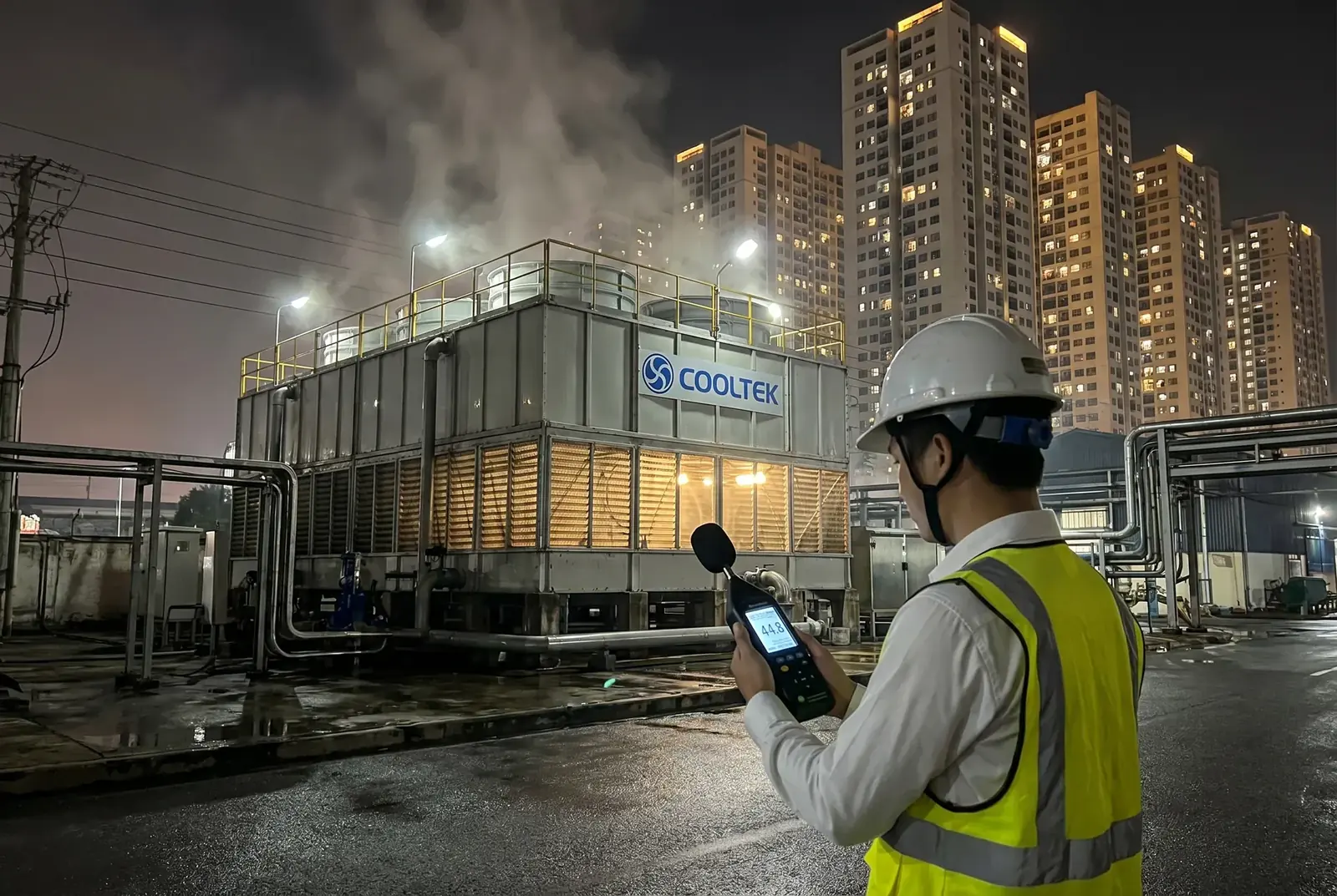
The LHR crossflow tower meets QCVN 26:2010 noise limits for residential and mixed-use zones, making it suitable for installation in urban industrial parks.
Reference standards: CTI ATC-105 cooling tower performance test code; ASHRAE 2019 HVAC Systems and Equipment Chapter 40; QCVN 26:2010 National Technical Regulation on Noise; ISO 3744 acoustics — determination of sound power levels.