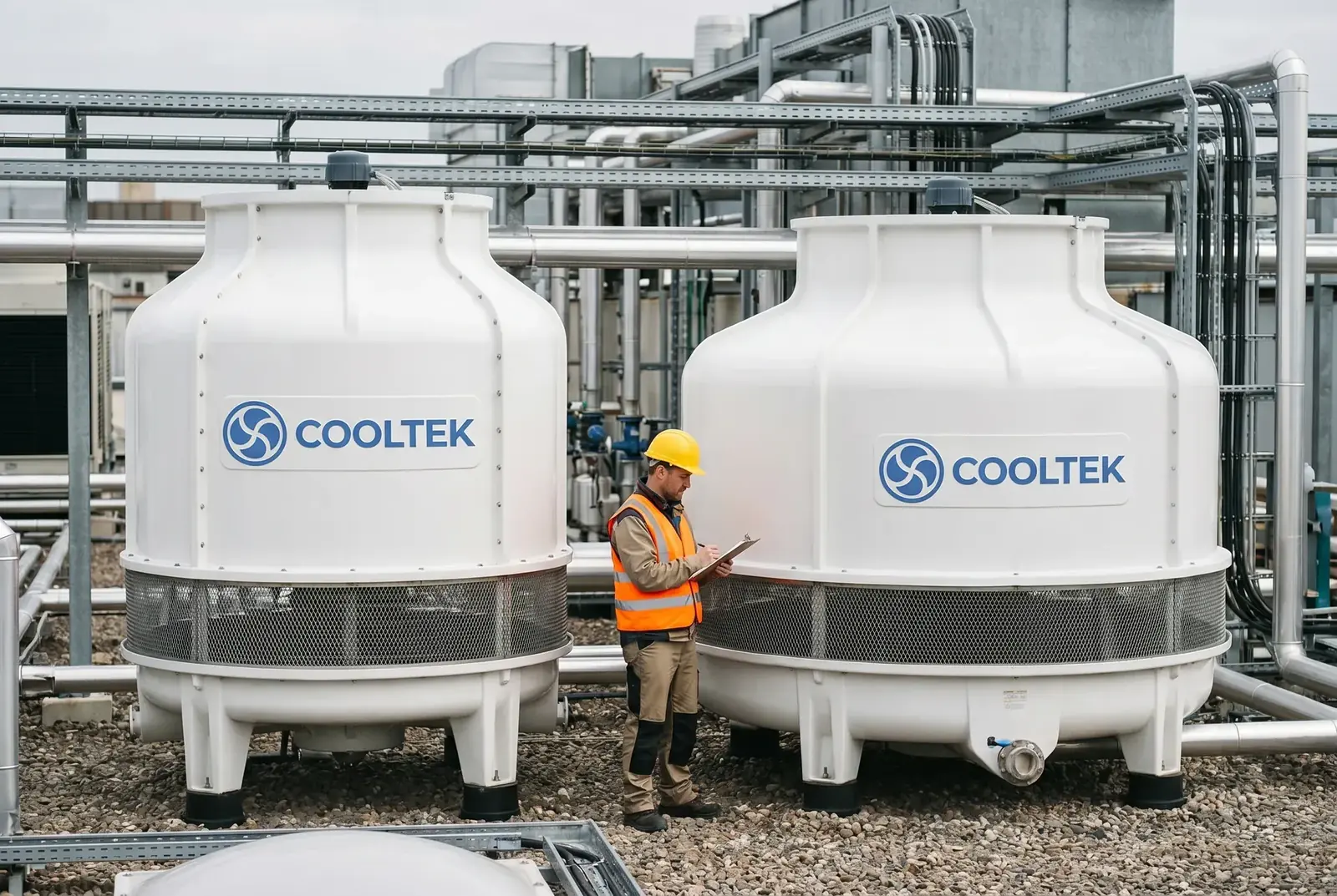
Figure 1: Small fluctuations in cooling water temperature are transferred to process equipment through heat exchangers, triggering material thermal stress and yield loss.
In a leading semiconductor packaging plant, process engineer Zhang is staring at a sharply falling yield curve on the screen. Over the past four hours, three consecutive batches from the molding workshop have shown product cracking, instantly turning hundreds of thousands of dollars' worth of chips into scrap. All production equipment parameters appear normal, the cleanroom temperature and humidity remain stable, and even the most experienced Japanese expert cannot identify the cause.
It is not until Zhang glances at the facility monitoring system that he notices a detail everyone has missed: during the period when yield dropped sharply, the cooling tower outlet water temperature on the plant roof fluctuated violently from the set value of 32°C down to 28°C due to a sudden rainstorm, and then quickly rebounded to 34°C after the rain stopped. This small fluctuation of only a few degrees was transferred through the heat exchanger to precision process equipment, becoming an invisible cause of chip failure.
In precision electronics manufacturing, plant managers are often willing to spend millions of dollars on advanced production equipment, yet they may compromise on a cooling system costing only a few hundred thousand dollars. What they may not realize is that an unstable cooling tower can undermine the work of an entire production line at any time.
Physical Principle: How Can a Few Degrees of Temperature Difference Crack a Chip?
To understand the destructive effect of cooling water temperature fluctuation on electronic equipment, we must look at the material science behind the process. In semiconductor packaging, such as chip bonding and molding, or in high-precision PCB manufacturing, the temperature-control accuracy inside the equipment is often required to reach ±0.5°C or even tighter.
When the outlet water temperature of a cooling tower fluctuates sharply, the fluctuation is quickly transferred to process equipment through the chiller or a direct cooling loop. According to the principle of thermal expansion in mechanics of materials, different materials, such as silicon chips, metal leads, and resin encapsulation materials, have significantly different coefficients of thermal expansion, or CTE. When the internal equipment temperature changes due to cooling water temperature fluctuation, these tightly bonded heterogeneous materials expand or contract by different amounts.
This inconsistent deformation generates significant thermal stress at material interfaces. When the thermal stress exceeds the yield strength or fatigue limit of the material, it can lead to microcracks, solder joint fractures, or even direct chip cracking. This is why, in semiconductor manufacturing, temperature fluctuation is often more destructive than a stable high temperature.
According to research in ASHRAE guidance for data centers and precision environmental cooling, for every 1°C deviation of cooling water supply temperature from its set value, the risk of precision equipment failure or yield loss rises sharply.
COOLTEK's Physical Solution: Holding the Temperature Limit with Counterflow Structure
When facing the near-zero-tolerance requirement for cooling water temperature stability in precision manufacturing, conventional crossflow cooling towers often cannot meet the requirement. In a crossflow tower, air and water contact each other at 90°. Heat-transfer efficiency is more easily affected by external wind speed, wind direction, and partial fouling of the fill. A gust of wind or a slight blockage in one side of the water basin can cause the outlet water temperature to drift by several degrees in a short period.
To hold the temperature fluctuation within the process limit, the COOLTEK LHN Series adopts a 180° counterflow heat-transfer structure, providing a physical solution for high-precision temperature control.
In the LHN counterflow design, air flows upward while hot water is sprayed downward, creating a fully opposite contact path. Thermodynamically, this structure provides the maximum temperature-difference driving force and ensures high stability throughout the heat-transfer process. More importantly, the LHN Series uses a pressurized nozzle water distribution system. Unlike the gravity basin of a crossflow tower, which can be affected by leveling conditions, pressurized nozzles force hot water into extremely fine and uniform droplets. Regardless of changes in external wind direction, the air-water contact area across the entire fill section remains highly uniform.
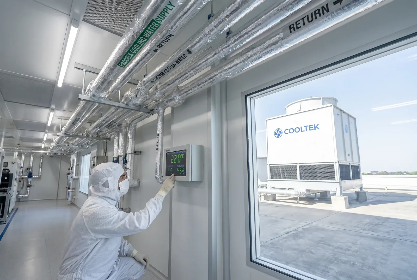
This heat-transfer design enables the LHN Series to keep the approach temperature between outlet water temperature and local wet-bulb temperature within a very small and stable range of 3–5°C. This means that even during unpredictable summer afternoons in Vietnam, the LHN Series can supply cooling water at the required set temperature like a precision instrument, keeping temperature fluctuation within the process tolerance limit.
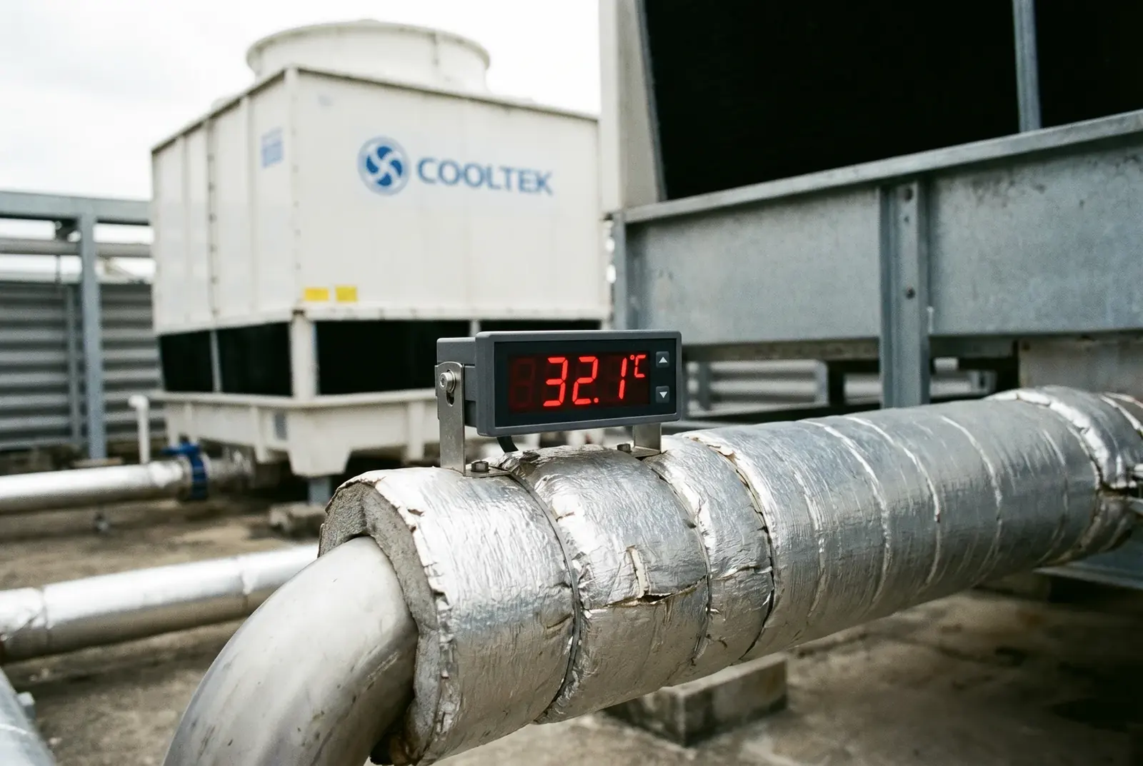
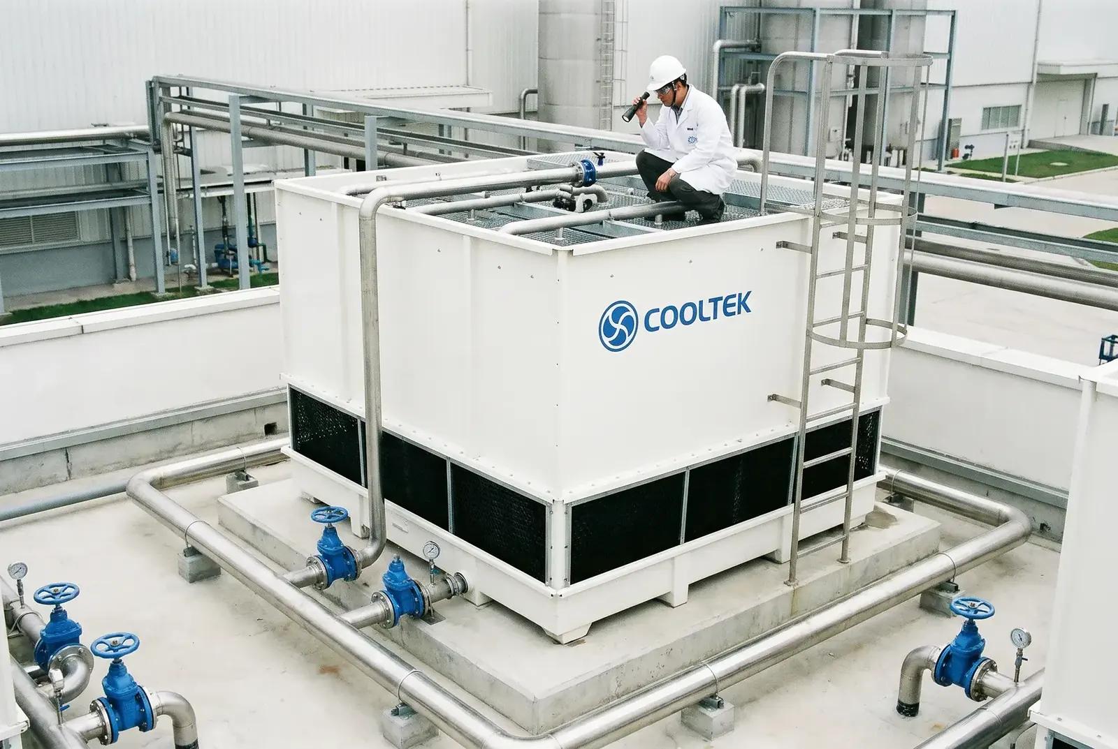
Figure 2: LHN counterflow structure — 180° air-water contact provides maximum temperature-difference driving force for stable outlet water temperature control.
At the same time, at a standard flow rate of 500 m³/h, the LHN Series has a footprint of only 25.00 m², saving up to 23.8% of space compared with a crossflow tower of the same flow rate. For semiconductor cleanroom surroundings, where land and equipment space are extremely constrained, this is a practical engineering advantage.
Industry Standard Verification: Strict Requirements for Precision Cooling
In precision electronics manufacturing, the cooling system must follow demanding industry standards. Facility standards issued by SEMI, the international association for semiconductor equipment and materials, set strict requirements for temperature stability, water quality, and pressure fluctuation in cooling water systems. Any cooling system that deviates from these requirements can become a major risk to high-value production lines.
For thermal performance verification, CTI STD-201, Standard for the Certification of Water-Cooling Tower Thermal Performance, is a globally recognized high-level test standard. QCVN 09:2013/BXD issued by Vietnam's Ministry of Construction also directly references this standard.
| Comparison Dimension | LHN Counterflow Square Tower | Conventional Crossflow Tower |
|---|---|---|
| Air-water contact method | 180° fully opposite flow, most stable heat transfer | 90° cross contact, more affected by external disturbance |
| Approach-temperature control capability | Very strong, stable within 3–5°C | General, usually above 5–8°C |
| Temperature fluctuation risk | Very low, with uniform pressurized water distribution | Higher, gravity distribution can be affected by local fouling |
| Applicable process scenarios | Semiconductor packaging, precision electronics, high-density data centers | Conventional injection molding, air compressors, commercial HVAC |
| Footprint at the same flow rate | Smallest, saving about 23.8% of space | Larger |
Reference standards: ASHRAE Thermal Guidelines for Data Processing Environments, 5th Edition; SEMI Facility Standards; CTI STD-201: Standard for the Certification of Water-Cooling Tower Thermal Performance.